Last
Top
Next

Prev
Top
Next
Introduction (to my website).
On this website I present all my projects with the AVR range of microcontrollers from Atmel. I like this microcontroller a lot because it of it's easy to use architecture and because there are lots of open source development tools available. And programmers also cost next to nothing. I built my first programmer with 5 resistors on a parallel port and I used it only once to program a better programmer: Application note: AVR910. Later I bought a kit for a faster and better programmer. The info on this website is meant for techies and other nerds who just like me love to play with these little critters.
All light blue projects in the menu (which are also the projects with the gray titles) are not yet implemented. The're just ideas for future reference.
Oh, and by the way, Avrfreaks is an absolutely great resource for these microcontrollers.
What you can learn here:

Prev
Top
Next
This is just an empty project to make it easier (faster) to start a new project.
- makefile A very simple self written makefile which I use for all my projects. It has no fancy auto dependency generation or other things which can be daunting to set up. It just has 46 lines of easy to understand code. The rest of the file is comment. This makefile should be edited to set the right cpu to be used and to link the right library's.
- main.h is linked with every library file of that project and therefore this is a good place to define all project dependent constants. Things to define in main.h are:
- What is the clock frequency used for this project. (F_CPU)
- Timer: Which resolution do we want to use for the timer library?
- Network: which pins are used for the RS-485 Driver?
- Some constants for the Transceiver Library.
- Lcd: How is it connected to the microcontroller? What size is it?
- Enabling or disabling some optional functions for the lcd and network libraries.
- main.c: A little scheduler. I use this to make the source code more readable for programmers.
Just a little framework to start a new project. It is a very simple cooperative multi-tasking scheduler which I have used for some of my projects. If you don't understand this framework I suggest to have a look at Network Alarm Clock which uses it for 5 different "tasks".
- _Check This.txt: A little reminder for everything I need to change to get a new project going fast.
- main.aps: Should make it a little bit easier to debug the project with AVR Studio.
- 2009-12 Added network stack to main because most projects use it.
Prev
Top
Next
This little library was initially written because I had some trouble with the reliable operation with my LCD library. If I chose another clock frequency for my AVR the timing was sometimes so far off that the LCD didn't work any more. Therefore I wrote some small functions: DelayUs( ) and DelayMs( ). Both functions just waste some time.DelayUs( ) Selects a little delay loop written in assembly. The actual loop chosen depends on F_CPU. Here is a snippet:
#elif F_CPU < 4500000                // Use a 4 cycle loop
"        subi       %0,2      ;Loop=4 Cycles, subi gains 2*4-1=7 Cycles. \n\t"
"1:      dec        %0        ;1 Clock cycle                \n\t"
"        nop                  ;1 Clock Cycle                \n\t"
"        brne        1b       ;2/1cycle"
        : "=r" (__count)
        : "0" (__count)
#elif F_CPU < 5500000                // Use a 5 cycle loop
Because this function compensates for the function call overhead, arguments smaller then 3 give unexpected results. This library has become partly obsolete lately because of the _delay_us( ) and _delay_ms( ) functions in GCC. Although these GCC functions are more accurate for most clock frequencies they do have 2 disadvantages. They can only be called with a constant argument. If _delay_us(a) is used then the whole floating point library gets pulled in which makes the timing very inaccurate and bloats the code unacceptably. The second disadvantage is that optimization MUST be enabled for these delay routines to work properly. Some weeks ago 2009-12 I changed of my projects to use the avr delay functions instead of my own delay lib. Strangely avr-size reported an increment in flash size of 100 bytes. This could be because my lib uses 2 functions while the code for the AVR delay lib is inlined in each instance where it it used.
Prev
Top
Next
When I wrote this library back in februari 2005 there weren't so many lcd library's on the internet as there are today.
Features.
- Databus: 4 bits (separate pins) or 8 bit (whole port). Configurable in main.h.
- Display sizes tested: 1x16, 2x16, 2x20 and 2x40. (Other sizes are easy to add.)
- This library depends on Delay.c. (Another, but very small library).
- with a single #define it can be forced to use the standard winavr delay functions.
- Code size 288 Bytes.
A step by step guide:
- Start a new project by copying the folder "_AVR_Main" to a new folder.
- Follow the instructions in the file "_Check_this.txt".
- Enable the libraries for delay and the lcd in the makefile.
- Start writing your own program.
For a list of available functions just look at the lcd.h file:
//---------------------------------------------------------------------------
void LcdWriteByte( uint8_t Data);  // Write a single byte to the LCD.
void LcdInit(void);                // Initialize the LCD.
#if USE_LCD_CLEAR
void LcdClear(void);               // Clear the LCD.
#endif
void LcdCommand(uint8_t Data);     // Send a command to the LCD.
void LcdSetCursor(uint8_t Pos);    // Move the Cursor around.
void LcdPutC(uint8_t Data);        // Write a single character to the LCD.
void LcdPutS(char *pS);            // Write a string to the LCD.
#if USE_LCD_PUT_X_HEX
void LcdPut1Hex(uint8_t C);        // Write a nibble to the LCD.
void LcdPut2Hex(uint8_t C);        // Write a byte (as 2 hex nibbles) to the LCD.
void LcdPut4Hex(uint16_t C);       // Write a int (as 4 hex digits) to the LCD.
#endif
void LcdWriteCgRam_P(uint8_t const *,uint8_t);        // Write custom char's to lcd.
Some predefined commands to write to the lcd are:
//---------------------------------------------------------------------------
#define LCD_COMMAND_SET_DDRAM_ADRESS    0x80
#define LCD_COMMAND_SET_CGRAM_ADRESS    0x40
#define LCD_COMMAND_FUNCTION_SET        0x20
#define LCD_COMMAND_SHIFT               0x10
#define LCD_COMMAND_CURSOR_ON           0x0E
#define LCD_COMMAND_CURSOR_BLINK        0x0D
#define LCD_COMMAND_DISPLAY_ON          0x0E
#define LCD_COMMAND_CURSOR_OFF          0x0C
A last hint: If you want to move the cursor of the lcd to the 5th character on the second line use:
LcdSetCursor( LCD_LINE_2+5);
This way you can move the cursor all over the display with only one argument in LcdSetCursor( ).
Prev
Top
Next
This little hardware timer library was originally written by Patrick Crombach who put it on the AVR Freaks website in the projects section as project number 221.
The software.
This library consists of just 3 little functions and uses up only 150 bytes of program space:
void Timer0Init(void);
int8_t TimerReached(int16_t *, int16_t);
int16_t TimerRead(void);
At program startup the timer must be initialized with Timer0Init( ). Every time the timer overflows an int16_t software counter is incremented in the timer interrupt. The resolution at which the timer runs can be set in main.h (TIMER_RESOLUTION) and must be between 10 and 50000 us. For a complete overview of all supported combinations of TIMER_RESOLUTION and the clock frequency of the AVR you can have a look at the timer.h file. Each timer needs it's own int16_t var to store the time value and that is the only limitation on the amount of timers you can use. In the following projects you can find examples on how to use this timer:
I made Crombach's timer a little smaller and more accurate and robust. But to keep it small I also deleted some functionality of his timer library.
Prev
Top
Next
Network Introduction.
The goal of this collection of projects is to completely define a network for (AVR) controllers and this is an ongoing project. This definition includes all layers of the OSI model. This includes: cables, connectors, Power supply and everything else needed to make a home network complete. It should be possible for anyone with a bit of programming and soldering experience to make a network node which can be directly plugged into a network somebody else made and have a high probability that it works immediately.
Some of the key features of this network are:
- Uses cheap, small, robust and easy to obtain RS-485 Drivers.
- Uses standard Cat-5 cable and connectors for power and communication.
- Wired connections are more reliable and secure then RF links.
- Network carries data and power to all nodes. No separate power supply's needed for each node. No batteries to wear out.
- Multi Master. (Anyone may initiate a communication on the network.)
- Collision Avoidance for less damaged packets on the network.
- Small overhead (6 Bytes header and 2 bytes crc).
- 16 bit addresses for all nodes.
- 16 bit CRC for packet checking.
- Variable data size: 1 to 240 bytes of payload for each packet.
- Low processor overhead for Packets for nodes which are not addressed.
- First byte of each packet is marked by sending it with 9 bits of data.
- The rest of the packet is send with 8 bits of data to shave of 12% of bandwith.
- Possibility for out of order communication for multiple packets. (Not used yet).
- Reliable operation with automatic resend of packets after timeout. (Optional _Network_Transceiver project).
- Standard baudrate (115k2) for easy connection to a PC.
- Debugging facilities with a network analyzer program on a PC (Windows and Wine).
- Small code size (920 Bytes for the network stack) and 568 Bytes for the (optional) Network Transceiver code.
- RF could be added in a later stadium.
Some Caution:
The original network code was developed for a AT90S2313. After switching to an AT90S4433 (now obsolete) the code broke because there are some subtle differences in the USART of that chip. The code broke because the switching between the first byte of a packet (9-bit data) and the rest of the packet (8-bit data) did not work properly. There is still a #define in the network code to force the code to work on an AT90S4433.
The code has been used / tested on:
- AT90S2313 (obsolete)
- ATTINY2313
- AT90S4433 (obsolete)
- ATMEGA8
- ATMEGA16
- ATMEGA32
Prev
Top
Next
There is lots of documentation written in the network.h file and I'm not going to repeat that all here. I'll just pick a few interesting things. There is no initialization needed for the network. Even though there is a NetworkInit( ) function. Because this function is so small and simple it is called every time a packet is send to the network. If the node does not send a packet very soon after startup but only listens for incoming packets it is wise to call the NetworkInit( ) function at the start of your program.
PacketMaxDataSize[ ].
Only one of these arrays actually ends up in the code. If the microcontroller is only expected to handle small packets and it receives a big packet the remaining bytes of the packet are automatically ignored because the array indexes which are meant for big packets are limited to the small packet size this microcontroller can handle. Note that the packet sizes are incremented in steps of 50%.
PacketSend(uint8_t *Packet).
The first task this function handles is to check if the microcontroller is already sending a packet. If that is so the function aborts with an error code (0). If that is ok, it checks the network for an idle state. The network is assumed to be idle if it cannot find any activity in a 100us period. That is slightly longer than the time to send 1byte over the network. Each byte has a start bit which will always be detected. If the network is idle the function aborts. If everything is ok the function sets the RS-485 driver in the transmit mode and writes the first byte of the packet to the uart and returns with an ok status (1). The rest of the packet is send by the uart data register empty interrupt. The only time a collision can occur on the network is if 2 nodes decide to start sending data at the same time. Because the time slot between deciding it is safe to send and the actual start of the transmission is very short ( Approx 0.5us @ 11.0592MHz) The only situation where it is likely that a collision occurs if when multiple nodes answer to a broadcast message. Some random delay could come in handy there.
Buffers.
Because most network nodes only have to handle small packet I usually use 2 buffers for packets. 1 buffer for sending packets and 1 buffer for receiving packets. If ram is to precious to do that it's possible to use the same array for both receiving and sending packets. The programmer is responsible for avoiding unintentional overwrites
Old vs new.
In november 2009 the code for the network stack had a big update. Before that date all packets were just defined as arrays. After that date packets are of type "TPacket". A structure with dedicated places for Adresses, Bitfields, Data and checksum. The old version is no longer maintained. It is here only because it might be used in some of my oldest projects.
Prev
Top
Next
Introduction
When I first had the sublime idea to build a home network (in Jan 2005) I had the problem of where to start. I decided that the network had to be connected to my PC. So that's where I started. My only experience with writing Windows software was a very simple terminal emulator to communicate with some of my microcontroller projects. This of course had the big disadvantage that only one microcontroller could be connected to a rs232 interface. Time for a change. I started work on a network analyzer / sniffer for my home network. I didn't need anything fancy, just the basic functionality for grabbing packets from and sending packets to the network. A year and a half later my application worked good enough to be useful. That is about the time I stopped working on the project, which means it never really got finished.
The Application.
When I started with my network sniffer I re used the code for my terminal program. You can still see that because the top window of the sniffer is still the terminal window of the original program. In the main menu there is also still a menu item for selecting all the different combinations of comport settings for a comport. This was useful for debugging in the beginning but at the moment this is a bit useless.
The menu.
 In the "File" menu item only the "eXit" button works. Very straight forward.
The second menu item "COM1:115200,8,n,1" shows the current comport settings. If you click on it there are 4 menu items which don't need any further explanation. Except for the "Settings" menu. That one has to be adjusted the first time for your configuration. If you select the "save" checkbox these settings are stored in the registry (along with the position and size of the main window) and you never have to worry about it again.
The third menu Item is just a small clock. It shows how long the comport is opened. If you click it the comport is closed and the clock stops running. If you click it again the comport is re opened and the clock restarts at 0.
The last menu item is for clearing the terminal and sniffer windows.
The Terminal window.
This was very useful in the beginning but that has ceased to be so when the sniffer window got further to completion. The program reads the buffer of the comport every 100ms and shows the data in the terminal window. This means that if there are 2 packets on a line they are read together in one buffer read. Sometimes when the network is busy a packet is split in 2 and is read by 2 consecutive buffer reads.
The Sniffer Window.
This is where all the packets end up. From left to right:
- A counter for the packet number.
- The time the packet is received from the network.
- The Destination address of the packet.
- The source address of the packet.
- A 4 bit packet counter.
- The Command flag.
- The Acknowledge request flag of the packet.
- The acknowledge reply flag of the packet.
- The Negative acknowledge flag of the packet.
- The number of data bytes int this packet.
- The 16 bit CRC.
- A check if the checksum was True or False.
- The data in the packet.
There is also a small edit functionality in this window. The delete key works and it's possible to drag the mouse over some packets and copy the data to the clipboard with the right mouse button.
The gray area between the 2 windows.
This area is for making and sending packets to the network.
From left to right:
- A checkbox for sending the current packet repeatedly to the network. This can be used for debugging on an oscilloscope or for stress testing of the network.
- The Destination address the packet has to be send to.
- The source address the packet is supposed to originate from.
- 4 checkboxes for the packet flags.
- A button to send the packet to the network. If this button is pressed a packet is generated and send to the network. The size of the data field is the smallest size in which all the data fits and the packet is always send with a correct checksum.
- A textbox for typing the data which is to be send to the network.
Improvements.
As stated before this program has never been finished and there is lot's of room for improvements. Some things which can (should) be improved are:
- Remove the terminal window.
- Improve synchronization (which is sometimes lost).
- Make a auto detection routine for the comport.
- The sniffer window is just a bunch of text. Packets should be logged in a linked list or something similar.
- If the packets are in a linked list you can do all kind of fancy things with them:
- Only show packets of a limited number of nodes.
- Show a list of erroneous packets.
- Do some statistics on the packets.
- Save packets directly to a log file.
- Read packets from that log file and resend them over the network.
- A proper driver for the network should be written.
Some notes for wine users.
 The main features of the network sniffer work under wine but for some unknown reason the menu does not work properly. This is not a very big problem because there is not much to do in the menu. Only the settings of the comport (which are wrong by default) have to be changed. You can do this by adding the following key's to the registry: HKEY_LOCAL_MACHINE-> SOFTWARE-> Hoeven Design-> NetworkSniffer
Settings for other com ports.
- com1 tty0 Setting REG_BINARY 00 01 0b 03 00 00 00 00 00 00 00 00 00 00 01
- com2 tty1 Setting REG_BINARY 01 00 0b 03 00 00 00 00 00 00 00 00 00 00 01
- com3 tty2 Setting REG_BINARY 02 00 0b 03 00 00 00 00 00 00 00 00 00 00 01
- com4 tty3 Setting REG_BINARY 03 00 0b 03 00 00 00 00 00 00 00 00 00 00 01
- com5 tty4 Setting REG_BINARY 04 00 0b 03 00 00 00 00 00 00 00 00 00 00 01
You would also like to add the font "VGAFIX.FON" to the windows/fonts directory.
Prev
Top
Next
 There are a few incompatibilities between a standard RS232 connection and my network and therefore an interface is needed. Voila: A new project is born.
The Hardware.
The PC cannot send directly to the network because all network nodes wait for a word with 9 data bits as the mark for the start of a packet and the PC can only send data with 8 bits of data. This could be overcome by some fancy programming in the PC and sending a carry bit with the first byte of a packet but I chose to take another approach because I noticed the RS232 drivers for windoze are a bit buggy and I wanted to avoid that mess. Therefore all data from the PC is buffered in a microcontroller. The microcontroller adds 1 extra bit to the first byte of a packet and simply retransmits the rest of the packet. All data from the network to the PC is simply level shifted RS485 levels to RS232 levels. This Generates some data overrun errors in the PC but we just ignore those because we know they are because of the extra 9th bit in the first byte of every packet. Unfortunately this also means that the PC cannot synchronize properly on packets because it does not receive the 9-th bit of the start byte from a packet but we solve that as best we can by detecting the pause on the RS485 lines between 2 packets
Two Interfaces.
If the network sniffer is running it uses a RS232 port from the PC. This means that that port is unavailable for other programs. This can be a problem if you want to debug the network part of another PC program. At the moment there is a simple workaround. I just built 2 network interfaces and they are connected to 2 different comports of my PC. A better way to do this is to write a proper device driver to handle the network traffic but I don't know how to write a device driver. This approach also has an advantage: I can monitor the network from my Windows PC and my Linux pc at the same time.
Software description.
The software is very straight forward. After some initialization an interrupt function writes all received bytes continually into a circular buffer. As soon as there is data in the circular buffer the main loop waits for 480us. After this small delay we check the amount of data in the buffer. If there's less than 4 bytes in the buffer we assume it is garbage and throw it away. This is needed because when the PC is turned off the RS232 line changes state and the PC interface interprets this as a start bit. If the received data is not garbage then SendAllData( ) transforms the data to a proper packet and sends it to the network.
//---------------------------------------------------------------------------
int main(void)
{
  PORTD=0x02;                     // 0 = RS485 Driver is Disabled TxD Idle = '1'
  DDRD=0xFA;                      // D3 = connected to RS485 Driver Enable
  DDRB=0xFF;
  UBRR=UART_BAUD_SELECT;          // Set baudrate for the Receiver.
  UCR=BV(RXCIE)|BV(RXEN);        // Enable RxD and int.

  sei();
  for(;;)                         // Executed once for every sent Packet
  {
    while(!CircularBufBytes())    // wait until there is enough data to send
      ;

    DelayUs(240);
    DelayUs(240);

    if( CircularBufBytes() < 4)
      CircularBufClear();
    else
      SendAllData();
  }
}
Prev
Top
Next

This is the simplest Network node possible. It's only ability is to turn a relay on or off. As a small extension there is also a pushbutton to toggle the relay. Because of it's simplicity it is an excellent example on how to write software for a network node.
The Hardware.
The hardware is pretty simple. There are 2 RJ-45 connectors, that way it's easy to daisy chain the whole network together. If you want some redundancy you can ad the (optional) transformer. This makes it possible to use the switch if the network is defective. In the past I've had some trouble with a clean power supply for my microcontrollers, since then I always put a little coil in the power supply. The other parts of the schematic are the microcontroller itself and the switch.
Software.
Let's have a look at main( ). Every time this node is reset it sends a welcome message to the network. After that it enters the main loop. There it checks every 10ms the state of the switch and toggles the relay if needed. After that it checks if a packet is received and if that is true the packet is examined and "executed" if it contains a valid command. After a packet is received the packetreceiver interrupt is automatically disabled to give the software time to examine the received packet. After the packet is handled the receiver is re-enabled again for the next packet. I'm a little bit paranoid, therefore I re-enable the PacketReceiver every time there was no traffic on the network for 10 minutes. If there is nothing to do the microcontroller is put to sleep.
//---------------------------------------------------------------------------
int main(void)
{
  int16_t Timer;
  static uint16_t IdleCount;
  DDRD = RELAY_OUTPUT;
  PORTB = 0xFF;                     // Enable Pullup.
  PORTD = (1<<3)|(1<<4);           // Enable Pullup.

  MCUCR|= 1<<SE;
  PacketDataSizeSet(MsgOut, 2);
  PacketChecksum(MsgOut);
  PacketSend(MsgOut);
  PacketReceiverEnable(MsgIn);
  Timer0Init();
  sei();

  for(;;)
  {
    if (TimerReached(&Timer, 1))    // Every 10 ms (1/100s)
    {
      ManualSwitch();

      if( PacketReceived())
      {
        IdleCount =0;
        HandlePacket();
        PacketReceiverEnable(MsgIn);
      }

      IdleCount++;
      if (IdleCount > 60000)        // Every 10 minutes of receiving nothing:
      {
        IdleCount = 0;
        PacketReceiverEnable (MsgIn);
      }
    }
    else
      asm volatile ("sleep");
  }
}
How to handle a packet.
Every time a packet is received it must be checked for valid info. There are 3 cases where we don't have anything to do with the packet:
- The packet has an invalid checksum.
- The packet is addressed to another node.
- The packet does not have a valid command.
If all these preconditions are met we execute the command: '1' turns the relay on and '0' turns the relay off. If the master wants a reply we send the current state of the relay back.
//---------------------------------------------------------------------------
void HandlePacket(void)
{
  if(!PacketChecksum(&MsgIn))
    return;

  if(!PacketIsForMe(&MsgIn, 0))
    return;

  if(!(MsgIn.Header.Flags & PACKETHEADER_FLAG_C))
    return;                        // if Command flag is not set.

  if (MsgIn.Data[0] == '1')
    PORTD |= PIN_RELAY;
  else if (MsgIn.Data[0] == '0')
    PORTD &= ~PIN_RELAY;

  if (MsgIn.Header.Flags & PACKETHEADER_FLAG_A)
    PacketSendReply(&MsgIn.Header.Source);
}
PacketSendReply( ).
This function formats and transmits a message to the network. First it sets the header of the packet, and then it adds a single data byte which has current the state of the relay. Then it calls the library function PacketChecksum( ) to add a valid checksum to the packet and keeps on trying to send the packet to the network until it succeeds.
//------------------------------------------------------Function Definitions.
void PacketSendReply(TAdress *Dest)
{
  uint8_t SendCnt;

  MsgOut.Header.Dest.Complete = Dest->Complete;
  MsgOut.Header.Source.Byte.High = NODEADRESSHIGH;
  MsgOut.Header.Source.Byte.Low  = NODEADRESSLOW;
  PacketChecksum(&MsgOut);

  for(SendCnt = 0; SendCnt < 100; SendCnt++)        // Stop infinite loop.
    if(PacketSend(&MsgOut))
      break;
}
Radiographic extension.
Nowadays it's easy to buy a set of radiographic controlled switches with a little 433.92MHz or 315MHz remote control. I hooked up one of those cheap AM receivers for the 433.92MHz band to my oscilloscope and I saw a perfect valid row of bits at 500Baud. The bits for the switch I tested are encoded in different pulse widhts for 1's and 0's very similar to the
DCF Clock. Because I actually measure the pulse widths of all the individual bits in that project it is an excellent base for setting up the RF-communication with those switches.
Below are a photograph of the witch and remote control I have (It's a 10 year old model) and a photograph of the 433.92MHz transmitter and receiver which can be used to control these switches.


Prev
Top
Next
Dimmer.
After a switch a light dimmer is one of the most common home automation nodes.
Some mental notes on the dimmer:
- Use a MOC4031 or similar for controlling the triac.
- Maybe use te sharp S202S01 solid state relay.
- Moc 4031 is limited in it's supply voltage: use a capacitive voltage divider.
- Use a simple opto coupler for zero crossing detection.
- Alternative: Use a 2nd atmel on the 230V side for the phase control. Serial communication through a single opto coupler.
Prev
Top
Next


Back in 2006 I also built a 2 channel thermometer which is connected to the network. This is the first time in my life that I used some fixed point math and that's why I wrote some help on how I did the 16.16 math in the software.
The measurement principle.
Before every temperature measurement the circuit is zero-ed by connecting the SWITCH_GND pin to ground and setting the SWITCH_VCC pin to input. This gives a constant voltage (adjustable with P1) on the input of the AD-converter. After enough time has passed to stabilize the circuit it is switched into sample mode. SWITCH_GND is turned into high impedance and SWITCH_VCC is set as an high output. This makes the current through the temperature sens transistor 11 times higher then it was before. This increment in current through the transistor translates into a higher voltage over the B-E diode in the transistor. This voltage DIFFERENCE is amplified approximately 100 times by an opamp before it is fed into the AD-converter. Because this voltage difference depends of the temperature of the transistor it can be used to calculate the temperature of the sensor. The reason for this somewhat strange measurement principle is that according to the theory the voltage difference should be linear with the temperature change which makes the temperature easy to calculate. The schottky diodes (bat85) are for protection. If the temperature sensor is disconnected the voltage over C1 (and C2) rises to 5V. If the temperature sensor is reconnected the voltage over the sensor is approximately 0.6V which gives a voltage of -4.4V on the other side of C1. Because this side of the capacitor is connected directly to the microcontroller this does all kind of nasty things to the circuit.
Calibration.
Because this is a one of project for me the whole thing is calibrated in software. The potmeter is only used for a very coarse adjustment for the temperature range that has to be measured. At first the sensor is put in melting ice water for a stable temperature at the low end of the range. Then the potmeter is adjusted to give a small reading on the AD-converter. This (averaged) value is hard coded and is the "TEMP_OFF_0" value in the software. After that the temperature sensor is put in boiling water to give a "hot" reading. This is the "TEMP_HOT_0" value in the software. From those calibration values the temperature is linearly interpolated or extrapolated.
The software.
If this is the first network related program you see then first have a peek at Network Switch . A lot of the software is similar to that project. The HandlePacket( ) function has a few more commands to handle the temperatures of the 2 sensors in fixed point or in human readable form (string). It can also send the raw value of the (summed) AD-converter. Something extra in this project is a watchdog reset if the network has been quiet for 12 minutes. There are of course also the ADC-routines and some functions for averaging, converting and formatting the output.
Prev
Top
Next
The alarm clock opens the roller blind in the living room every morning and closes it every evening. The atmel controls a motor from a little accu drill to control the position of the roller blind. Because the network can't deliver enough power I run the motor from the batteries which came with the drill. Every few months when the batteries are getting empty I type in a little network command which activates a charge pump which charges the batteries. It takes about a week to recharge the batteries and then the charger automatically shuts itself off. To prevent having to build a full bridge I just use a simple relay to control the direction of the motor. The speed of the motor is controlled by a PI controller in the micro. Position feedback is from a little encoder disk I glued onto the motor shaft. This setup can run for months without having to adjust the position of the roller blind (There are no end switches). On the schematic there is also an connector for an Lcd which has only been used for debugging during development.
The Software.
There are 2 interesting parts in this software. The first is a interrupt function which takes it's input from the encoder and keeps track of the position of the roller blind. The second is the PI controller. The PI controller actually has 2 nested loops. The inner loop for the speed of the motor and an outer loop for the position. Note that overshoot in this application is unacceptable because of the simple setup of the motor control (Just 1 power fet and a relay) and therefore the deceleration of the motor must be slower then when it slows down on itself without power. Braking the motor would mean activating the reverse realy and that would mean the motor would brake very hard because it is shorted via the freewheel diode. And I actually like it to see the roller blind decelerate slowly until it reaches it's end position.
The Commands.
A list of all commands which this network node can handle:
- 'b' Current position is bottom positon.
- 'c' Turn on the battery charger for 7 days.
- 'd' The roller blind goes down.
- 's' Stopmovement.
- 'u' Move the roller blind Up.
- 'z' Current position is Zero position.
- '?' Send some packets with the user manual.
- '+' Move the roller blind a little bit down.
- '-' Move the roller blind a little bit Up.
The Movie Screen.
After the roller blind in my living room was working properly for about a year and a half I decided is was time to motorize the screen of my beamer. This project is not finished yet (2010-03-11) but it's getting along pretty well. For this project I made some hardware and software changes. You can see the hardware changes by comparing the 2 schematics above. Differences in the software are made with:
#define PROJECT_NUMBER 1
The main differences are:
- Different network adress.
- Different PI parameters and distance to travel for the motor.
- Added an switch for automatic calibration of the top position.
- Removed the battery charger. Both roller blinds motors are powered now by the same 500VA 12V transformer. After these projects are finished they will be powered by the
- Added galvanic isolation (opto coupler) between the motor and the micro controller. This also puts more voltage on the gate of the MosFet to turn it more on.
- Used standard connector for debugging lcd.
- Added a diode between the PWM output and the reset line to prevent the motor from turning on while programming the node.
- Added an electro magnet to block the rollerblind because the movie screen is so heavy that when the motor is unpowered and the screen is in the down position it unrolls all by itself untill it hits the ground.
- Added an extra pecaution: If the motor does not rotate within a second after applying power it is assumed the motor is blocked (Usually by the electro magnet, I'm still debugging this.) and the motor is turned off again. I blew up 2 Fet's (BUZ10) because te fet has a small heat sink and overheats quickly if the motor is blocked and more than 10A runs through the FET and motor. Overheating of the FET can probably also be limited by designing a better gate circuit for the FET to turn it on and of faster during the PWM.
Prev
Top
Next

This is one of the first projects I made which connect to the network. I bought a cheap little Dcf clock (EUR8) and I took it apart the moment I got home. After playing a bit around with my scope I quickly found a wire to tap the DCF signal from. Another thing I found out was that the DCF signal was not continuously available but that was also quickly fixed with a bit of solder. Threw in an AVR and a RS-485 driver and some bits and chips for a power supply and a level converter for the DCF signal and the hardware was finished.
The Software.
The software took a bit more of my time and some thought. I don't know if other people read the dcf time in a similar way as I do but I'd like to think I came up with a neat little algorithm. I do not sample the bits but I measure the time between the flanks of the dcf signal with an external interrupt on pin change. This gives just a few possibilities: A time of 100ms is a logic zero, a time of 200ms is a logic one. 800 or 900ms is the time between 2 bits and 1800 or 1900ms is a skipped pulse and the start of a new minute. Because each pin change is carefully monitored (and a tolerance can be set with PULSETOL) this is far more accurate than the parity bits in the data stream and therefore I ignore the parity bits. If a skipped pulse is detected and we counted 59 bits we assume the time is received correctly and we copy it to the internal clock. That was the first part of the algorithm. In the second part of the algorithm (the big switch) we put the received bits in a buffer (the structure Dcf) every time a nibble is received we copy that nibble to the right place in the time structure. Unfortunately the DCF clock has a bug at this moment (April 2009) sometimes it resets itself when it shouldn't. I'm not sure whether this is a software or a hardware bug.
//---------------------------------------------------------------------------
/* Interrupt routine called on every pin change.
DCF bit times should be 100ms for logic 0 and 200ms for logic 1 but my receiver
has bit times of approx. 90 and 180 ms. TIMER_RESOLUTION is 2.5ms Which means
there are 400 ticks in a second. */
SIGNAL(SIG_INTERRUPT0)
{
  uint8_t Dummy;                // BitBucket for useless data.
  int16_t TimeDiff;
  int16_t NewTime;
  static int16_t OldTime=0;
  static uint8_t Error=0;        // Set on receiver errors.
  static uint8_t BitCnt=0;        // Number of bits received for this minute.
  static uint8_t *pTime=&Dcf.Minutes;// Start for Storing incoming bits.

  NewTime = TimerRead();
  TimeDiff=NewTime - OldTime;
  OldTime=NewTime;

  // My dcf clock has a bit different pulse widths as the official dcf protocol.
  if(  (TimeDiff > 40 - PULSETOL)
     &&(TimeDiff < 40 + PULSETOL))        // 100ms Pulse=logic 0
    ;
  else if(  (TimeDiff > 73 - PULSETOL)
          &&(TimeDiff < 73 + PULSETOL))// 200ms Pulse=Logic 1
    ;
  else if(  (TimeDiff > 316 - PULSETOL)
          &&(TimeDiff < 372 + PULSETOL))// 800 or 900ms Time between bits.
    ;
  else if(  (TimeDiff > 716 - PULSETOL)
          &&(TimeDiff < 804 + PULSETOL))// 1.8 or 1.9s = Skipped pulse.
  {
    if((BitCnt==59) && (Error==0))        // If we read all bits without error:
    {
      Synchronized = 1;                // Seconds since last sync, but cannot be 0.
      Dcf.Seconds   =
      Dcf.Hundredths = 0;
      Dcf.WeekDay--;                // Weekday is 0...6 instead of 1...7.
      memcpy(&Clock, &Dcf, sizeof(TTime));        // Copy Dcf to Clock
      memcpy_P(MsgOut+PACKETHEADERSIZE, StrSync_P, sizeof(StrSync_P));// Debug.
      PacketDataSizeSet(MsgOut, 4);
      Status |= FLAG_DEBUG_SEND;
    }

    BitCnt=0;                        // Fresh start for the next minute.
    Error=0;                        // No errors at start of a minute.
    pTime=&Dcf.Minutes;                // Start storing data with minutes.
  }
  else                                // Else: TimeDiff has an illegal value.
  {
    Error=1;                        // We encountered an illegal pulse with.
    if(Status&FLAG_DEBUG)                                        // Debug
    {
      itoa(TimeDiff,(char*)MsgOut+PACKETHEADERSIZE,10);        // Debug
      Status|=FLAG_DEBUG_SEND;                                        // Debug
    }
  }

  if(TimeDiff<100 + PULSETOL)        // <200ms, we read a bit from DCF receiver
  { // Set a pointer to where to store the Dcf databits
    switch (BitCnt)
    {
    case 29:                        // If we stored the minutes
      Dcf.Minutes&=0x7F;        // Erase parity bit
      pTime= &Dcf.Hours;        // Start Storing Hours
      break;

    case 36:                        // If we stored the Hours
      Dcf.Hours>>=1;                // Hours are coded in 7 bits.
      Dcf.Hours&=0x3F;                // Throw parity bit away
      pTime= &Dcf.Days;
      break;

    case 42:                        // If we stored the day (of the month)
      Dcf.Days>>=2;
      pTime= &Dcf.WeekDay;
      break;

    case 45:
      Dcf.WeekDay>>=5;
      pTime= &Dcf.Months;
      break;

    case 50:
      Dcf.Months>>=3;
      pTime= &Dcf.Years;
      break;

    case 58:
      pTime= &Dummy;                // Make it point to a harmless place
      break;
    }

    *pTime>>=1;
    if(TimeDiff > 40 + PULSETOL)// Time was logic 1
    {
      *pTime|=0x80;                // Store the DCF bit in the msb of *pTime
    }
    BitCnt++;
  }
}
The commands.
The commands for this clock are mostly single letter packets. I tend to use lower case letters for human readable format (easy to type into the Packet sniffer) and upper case for binary formats.
- "d1" or "D1" Turns debugging information on.
- "d0" or "D0" Turns debugging information off.
- 's' Return the time in seconds since 2000-00-00 as a string.
- 'S' Return the time in seconds since 2000-00-00 as a uint32_t (little endian).
- 'M' Return the time in ms since 2000-00-00 as a uint64_t (little endian). (Not implemented yet).
- 't' Return the time as a string. Example of the format: "2006-10-25Wo21:53:22"
- 'T' Return the time as a structure (with an resolution of 1/100s.
- 'y' Return the time in seconds since the last synchronization (string).
- 'Y' Return the time in seconds since the last synchronization (uint32_t little endian).
- On any other received packet an error message is returned.

 -
-
As a last thought about this project I want to share some pictures of the electronics in the clock. If the pcb was any bigger it wouldn't fit into the casing. There wasn't any room for the 2nd RJ-45 connector and at that time I also didn't know that 2 of those connectors is a smart thing to do. The ISP connector is accessible through a slit in the case so I don't have to take the box apart to reprogram the microcontroller.
Prev
Top
Next
 This project is a clock with a big and clear display (70mm x 280mm). For size reference: On the left side of the 7-segment displays there is a standard AA battery. This clock is capable of storing / executing 32 different programs.
Each program consists of:
- Byte where each day of the week has it's own bit.(Any combination of week-days is possible).
- Byte (Packed BCD) Hours.
- Byte (Packed BCD) Minutes.
- 6 Bytes of data for a packet to send to the network.
- 16 Bit destination adress for the packet.
This is the first program in which I used all of my standard libraries together:
Network,
Lcd,
Delay,
Timer and
Network Transceiver and the total code sizeof this 10368 Bytes.
One of the challenges of the design of this clock was that there are 5 different "tasks" which all need regular attention. but when I started this project my programming skills were limited to one main task and a few interrupt routines.
- Keeping track of the time [@100Hz].
- Multiplexing of the display[@1kHz].
- Reading the state of the buttons[@34Hz].
- Manage the link with the network[@76Hz].
- Update the content of the display's[@9Hz].
I chose these randomized frequencies to divide the execution of each task more evenly over the available processor time.
After some thought I came up with the idea of using sort of very simple "task switcher". This switcher is nothing more than a for loop which checks every timer tick (from the Timer lib) if one or more of the tasks is due to run. The tasks are executed via a function pointer. Because the main loop starts again with searching for a task to execute every timer tick, the tasks have a natural priority: the order in which they are in the list. This scheduler works so good that I later added as a standard component to the _Main project for use in all future project. If it's not needed it is deleted again with just a few mouse clicks.
The Hardware.
For a project like this a lot of pins are needed if everything is driven directly. To save some pins I used 2 simple tricks.
- Port C is used as a generic data bus and connects to 3 other IC's. The LCD, A buffer for the Common Cathodes of the 7-segment display's and for the segments of the displays.
- Another common trick is to use multiplexing for the 7-segment displays.
To make the brightness of the 7-segment displays (which need 8 Volts because each segment has 3 led's in series.) the same as the leds for the days of the week, I use current sources for the segments. To compensate for the multiplexing (less brightness) of the display the current sources are set to a current of 0.6V/15 Ohm = 40mA. Which is more than the display's can handle continuously. On the left of the schematic are the Lcd display ( With a charge pump to generate a negative voltage for the contrast), the network interface (with 2 RJ-45 connectors) and the microcontroller (atmega16) which controls everything. Because I have had some problems with spontaneous resets with some projects in the past I have learned not to trust on the internal pull-up resistor of the reset pin. I always add an external pull-up resistor. To make the schematic complete there are also a crystal, a voltage regulator for the LCD and ATMEGA16 and the layout for the connector I use to connect the 7-segment displays to the PCB. The white connector is for the LCD.
The Software.
Keeping track of the Time.
To synchronize the time nicely we keep track of time in 10ms increments. That means that if a packet is received from the network to synchronize the time, the times are so near to each other the seconds change at virtually the same time. From this 10ms reference we increment the seconds, minutes, hours and weekday. At the start of every minute it checks if any alarms are due and if so it sets a flag to service those alarms which are thereafter handled by the network thread. Because the world we live in is not perfect this function also makes some small adjustments to correct the speed the clock runs.
Multiplexing the display.
In the array MultiplexDisplay[] are all the segments for the 6-digit 7-segment display's and for the leds for the day's of the week. We just increment a counter each time the loop executes and write the bit pattern for the new display to the outputs. Because the displays are pretty big an I had to use some external (and slow) transistors to control the displays a few very small delay routines are inserted. Without those delays there is some "ghosting" on the display's.
The Network.
The network task has two functions to perform. It synchronizes the clock with a reference from a DCF clock and it sends packets over the network if alarms are due. The packet transceiver is used for both these tasks. For the alarms the transceiver just wants a reply from the remote node and therefore the callback function is not needed. If it's task is to synchronize the clock then it expects a packet which contains the time (in packed BCD format). This packet is given to the callback function which sets the current time accordingly.
The Buttons.
This alarm clock has 4 push buttons to adjust it's settings and ThreadButtons( ) handles them. It is a small thread and it performs a few simple functions:
- Read the state of the buttons.
- Debounce the buttons read.
- A repeat function if the buttons are held for a short time.
- It updates a variable for making the display blink.
The user interface.
The user interface is handled by the function ThreadUpdateDisplay( ). This function handles the input from the buttons (The global var Buttons). and updates the content of the display's accordingly. This user interface was a bit more complex than I first anticipated and took quite some time to debug. The layout of the 4 buttons is the same as the cursor keys of a normal 101-key pc- keyboard. In the middle are an "up" and a "down" button. On the left there is a "left" button which also serves as an escape or cancel button if is pressed repeatedly. And as you might have guessed, on the right there is a "right" button. This last button is also used as an "enter" or "confirm" button if it is pressed if the cursor is at the most right position of the display.
Adjusting the current time.
Regardless of the state the clock is in, if the "left" button is pressed repeatedly you always go back to displaying the current time. If then the "right" button is pressed one of the "day of the week" leds blink and the weekday can be adjusted with the "up" and "down" keys. Press the "Right" button again and the Tens of the hours start blinking and can be adjusted. Same for "Hours Units", "Minutes Tens", "Minutes Units", "Seconds Tens", and "Seconds Units". If the "Right" button is pressed if the cursor is on the "Seconds Units" display the newly entered time is copied to the clock and the clock starts counting from there.
Adjusting the alarms.
If the clock is displaying the current time and the "up" or "down" buttons are pressed the clock shows one alarm out of the list of alarm. The number of the alarm is in the place the seconds are normally displayed. At the moment there are 9 possible alarms. Adjusting the alarms is very similar to adjusting the current time. When an alarm time is on the display press "right" to start editing that alarm. The days of the week are handled differently when programming alarms. "left" and "right" go through the days of the week, an "up" or "down" toggles the currently selected weekday on or off. This means you have to press "right" 7 times to start adjusting the "Hours Tens". Adjusting the Hours and minutes works the same as with the clock, but there are no seconds. When pressing "right" if the cursor is on the "minutes Units" digit the cursor moves to an lcd display on which the network address and the data of the packet can be adjusted. The first 4 digits of the lcd is the (hexadecimal) adress of the node to which the packet has to be send, then comes a space, followed by 6 digits for the command which has to be send to the remote node. Data for the commands can be: 0-9, a-z, and A-Z and a space. When the cursor is on the 6th digit of the command and "right" is pressed the alarm time with it's adress and packet date are stored in the ram of the clock and a copy is saved in eeprom. The eeprom is read at power up of the clock and copied to ram. If you changed your mind during entry of any data just press "left" repeatedly untill the normal time shows on the display and none of the settings will have changed.
Improvements.
This project is running since 2009-03-29 and is now (2010-02-20) still running fine. But there is always room for improvements. Some things I thought about are:
- Add a light sensor and dim the display in the dark.
- Make a nice box to put everything in. I have a workshop available for that kind of work, but I don't want to go there in winter.
- The backlight of the lcd (or the whole display) can be turned of if there is nothing to show. Since the lcd display is only used for changing alarm addresses and commands it can be off for about 99.9% of the time and this will save some power.
- Because of the big 7-segment displays the clock uses about 500mA of supply current. This is half of the total power the network can deliver. Maybe give it it's own power supply. (which can also deliver power to the network).
- Go back to displaying the time if there is no user input for a few minutes?
- Put on an antenna to pick up the 50Hz mains frequency for keeping time without DCF.
- Use external sync sources to calculate the internal clock deviation and correct for this.
- Bug: Can go wrong is clock is updated at the same time an alarm is due, there is a possibility that the alarm is never executed.
Prev
Top
Next
Network Breadboard Interface.
Schematic

This mini project really helps in trying out some new ideas fast for network nodes. It is a little pcb which connects to the network on one side and on the other side it provides some signals to directly hook up an AVR to the network.
On the board there are also connections to measure the current consumption of the connected circuit (with 3 selectable shunt resistors. 1, 10, or 100 Ohm) and a connector to directly tap into the network signals.
Prev
Top
Next
The purpose of this library is to ad a certain degree of reliability to the network. It is a state machine which will resend a packet a preset number of times (with exponential increments in the time delay) if it does not receive an acknowledge from the addressed node. If an acknowledge is received an (optional) function is called with the address of the received packet as parameter.
The State machine.

The state machine is not very difficult, it only has 8 different states. Every state is written in it's own function and switching between states is done by changing a function pointer. The whole state machine is drawn within the big circle. The interface between the program and the state machine is drawn outside the big circle. The single characters between quotes are for debugging. States which allow the state machine to exit are marked with an arrow which is labeled with "run = 0". All other states change the function pointer SMState immediately to one of the other states. The only delay in the state machine is when a packet has to be send to the network. PacketSend() checks for 1 byte time (approx 100us) if the network is idle before it sends the packet to the network. If PacketSend() fails it tries a maximum of TRANSCEIVER_SQUEEZE_TIMES to send the packet before it aborts. The rest of the timing of the state machine is determined by the delays between the calls of the TransceiverRun() function.
The api.
The api of this library is very simple and consists of just 3 functions.
- void TransceiverRun(void).
- void TransceiverStart(TCallback,uint8_t*).
- uint8_t TransceiverStatus(void).
void TransceiverRun(void)
This is the function which makes the state machine tick and should be called at (somewhat) regular intervals. (Every 1 to 200ms is usually ok). To short an interval does not give the addressed node enough time to respond before the first resend. And to long an interval just makes everything real slow. TransceiverRun() starts by setting the STATUS_RUN flag to indicate that the state machine is running. After that it just keeps calling states until the run flag is cleared, and then it returns. The current state is responsible for clearing the STATUS_RUN flag or for changing the function pointer to another state. This construction makes it possible for several states to be executed before the state machine returns.
void TransceiverRun(void)       // Run the Statemachine, call this repeatedly.
{
  Status|=STATUS_RUN;

  while(Status&STATUS_RUN)
    SMState();                  // Execute the current/new state.
}
void TransceiverStart(TCallback Func,uint8_t *Packet)
This function must be called to initialize and start the PacketTransceiver. It's arguments are a pointer to the callback function and a pointer to the packet which is to be transmitted to the network.
uint8_t TransceiverStatus(void)
This function reads the internal status of the state machine. This status consists of 3 bits in an uint8_t. The bits are:
- STATUS_RUN This bit only has an internal meaning to the state machine. The function TransceiverRun( ) sets this bit and will keep executing states as long as this bit is set. It will be very unlikely that this bit is ever set if TransceiverStatus( ) is called. (Unless TransceiverStatus( ) is called from the CallbackFunction.)
- STATUS_ERROR This bit is set if an unrecoverable error is encountered. For example if the maximum number of resends has been reached.
- STATUS_IDLE This bit indicates that the whole state machine has finished with it's job and is waiting for another initialization with TransceiverStart( ).
- STATUS_STOP This is not really a bit. It is the absence of any status bits. If the state machine is halfway it's job and want to clear the STATUS_RUN flag it just sets the status to STATUS_STOP. This is a few bytes smaller then clearing only the STATUS_RUN flag.
The Callback Function.
If the callback function is used it is called rom the Callback state if the state machine has received a valid packet from the remote node. This is used as a simple example in the Network Alarm Clock project. For more complex communication protocols which need multiple packets, the callback function can build the next packet and call TransceiverStart( ) to send that packet away and the new packet will be send immediately to the network.
Debugging.
There is lots of debugging info in the code, but it is all disabled with a single #define. If debug info is turned on then all the single letter text such as 'R' or 'X' in the state machine diagram are written on every state change to an lcd.
Global variables.
The state machine uses some global variables. All these variables are declared as static and therefore they are only visible in the state machine file itself. A list of these global variables is in the top of the file Transceiver.c.
Prev
Top
Next

This project has been ongoing for more then 25 years. Every 5 years or so I take it out of the closet and do some work on it. The ultimate goal of this project is to build a small 3d milling machine for milling out pcb's and other small stuff. When I started this project It was very ambitious (I think I was about 15 years old). Nowadays the Internet is full of similar projects. Most of those projects use a mix of self build hardware and already build software. I am a bit stubborn and want to design it all myself. Sometimes I cheat a little bit. I still need a good and simple algorithm for radius compensation...
The Hardware.
There is so little hardware it isn't worth putting an schematic on the internet. It has an ATMEGA16 with my own network interface and 4 times the 2-bit u Stepper because the y-axis has 2 stepper motors. Things like end switches and other safeties and tool bays for automatic tool switching are not built yet. Don't be fooled by this simple hardware though. The project is far enough to make some test run's. Here are the pictures: 

The Software.
The software for this project is divided in 2 parts. A program for the microcontroller and a PC program. Each program is designed for the part of the job it does best. The PC software is good and fast at things as file transfer, calculations and interpretation visualization and translation of commands. The embedded software is kept as simple as possible and only does what it's good at: Sensitive timing stuff.
The PC Software.
This is by far the part which needs the most work.
The programming language.
For this program I have designed my own programming language. This is a very simple language which looks somewhat like assembly language. This language has 3 big advantages over the standard G & M code which is normally used for machines like this.
- It can "include" files. Those file can be calibration settings for the machine or even whole drawings in hpgl format or later possibly G & M, svg or gerber files.
- It has subroutines.
- It has loops.
To explain the basic structure of this programming language I have made a little example program which explains how it works.
; This is a line of comment because everything after a ";" is comment.

; Test program for milling a little square.
; Mainly useful as an example of how to use the commands.

        start                   ; The start point of the program.

        include "initialisation.mil"

        abs                     ; Coordinates are absolute now.

        pd                      ; HPGL command. This draws on the screen.
        tool    3               ; Use tool nr 3.
        rpm     10000           ; Spindle Speed is 10000 rpm.
        feed    30              ; Milling is done with a feedrate of 30mm/min.
        spon                    ; Spindle on
        movf    100.5 200,12    ; Move fast to position: x=100.5 y=200.12
                                ; Dots and comma's are treated the same.
                                ; Parameters are separated by whitespace.
                                ; Fraction is truncated to 3 digits.
        rel                     ; Use Relative Coordinates from now on.

        movf    0 0 -23         ; Move fast to just above the material.
        mov     0 0 -2          ; Move with feed rate speed ( 30mm/min ).
        gosub   square          ; Mill a little square in the material
        gosub   square          ; Make the square a little deeper.

lab1:   gosub   square
        loop    lab1 10         ; Loop 10 times back to label lab1.

        mov     0 0 5           ; Move 5 mm up, Tool is (just) above material.
        movf    0 0 30

        abs
        movf    130 200 23      ; Move the Tool away from the material.
        gosub   Hello_world     ; Now do this subroutine.
        spoff                   ; Turn the spindle off.
        end                     ; End of program. (Not needed?)

; Subroutine for making a little square hole.

sub     square                  ; Start definition of a subroutine.
        mov     0    0  -1      ; Move 1  mm down.
        mov     10   0          ; Move 10 mm to the right
        mov     0   10          ; Move 10 mm in Y direction
        mov     -10  0          ; Move 10 mm to the left.
        mov     0  -10
        return                  ; End of subroutine.

sub     Hello_world
        include "Fonts\Verdana.mil"; include subroutines for the whole font.
        gosub   H e l           ; Call the subroutines: "H", "e" and 'l'.
        gosub   l l o space w o r l d dot

; The subroutines for the letters must do something like:
; 1). pd
; 2). move a bit around.
; 3). pu
; 4). move to the start of the next letter.
        return
There are some more commands which are not in this example. Some of these are:
- simon ___ Simulation On. Draw on VGA but do not move the mill. Lines on the VGA are dotted, not solid.
- simoff ___ Turn Simulation off.
- color ____ Set drawing color for R, G, and B. (only on VGA).
- master __ Switch to the master coordinate system.
- tool _____ For changing the tools (not implemented yet).
- org _____ Use the current position in the master coordinate system as the origin (0,0,0) for the absolute coordinate system.
The Embedded Software.
The embedded software is kept very simple, it doesn't know about coordinate systems, it doesn't know what a circle is, it doesn't know what radius compensation is, etc. All it knows are some basic linear move commands, Speed limits while moving and acceleration and deceleration of the stepper motors. When searching for algorithm's for acceleration for stepper motors I found an article written by D.Austin on www.embedded.com . It is an excellent algorithm for controlling stepper motors and it uses only one division for calculating the delay for the next step. Some time later this article was adopted by Atmel in their design note 446 and it can also be found on lots of other places on the internet. After some experimentation with this code I decided is was overkill for this project and I settled for a simple look-up table for the delays. Just recently I found an article which claims to be even simpler than David Austin's but I haven't tried it yet.
Main( ).
Just a little function which accepts commands from the network and writes them into a circular buffer. If there are commands in the buffer then main( ) executes them. All commands which move the motors eventually end up in the function BresenhamStep( ). This function translates the move commando's to step bits for the motors and delay's for the interrupt routine and writes those to a second circular buffer.
Timer1.
The interrupt associated with this timer is used to generate the step and direction pulses for the stepper motors. It reprograms itself with different delays to change the speed of the motors. If it has nothing to do it reprograms itself to a low interrupt rate untill there is some action going on. This interrupt routine takes it's input from the step buffer which is filled by BresenhamStep( ).
The Commands.
In the file frees.c are all stepper commands which are supported by this little program. Most of these commands end up with calling BresenhamStep( ) which writes moves to the step buffer. All commands with only the content: "CommandFunc=NULL;" are discontinued or not implemented yet.
Mr.Bresenham invented a really ingenious algorithm do transform a line into something representable on a raster. His line drawing algorithm is quite famous and I'm not going to explain here how it works. A small limitation of the original algorithm is that it only works on 2 axis. The simplestt way to add more axis is to introduce an extra variable. That variable is simply set to the axis with the most movement and is the variable which is used for every step iteration of the algorithm. This way it is easy to add as many axis as you want to the algorithm.
ToDo
Mechanical.
- Mount the cast aluminum base to the mill.
- Connect end switches.
- New spindles for the motors.
- A better spindle motor.
- Add a vacuum cleaner for the debris.
- Add an enclosure for the electronics.
- Build something for automatic tool change.
Embedded Software.
- Implement some more commands. (spindle motor/vacuum cleaner on/off etc).
- Implement the end switches.
- Implement a function for lining up the 2 stepper motors for the Y-axis.
Prev
Top
Next
Dcx 2496.
This little box is a loudspeaker management system made by Behringer. It has 3 analog inputs and one stereo AES/EBU digital input. (shared with an analog input). It also has 6 outputs to connect 6 amplifiers and 6 speakers. The main disadvantages of this box is the low quality of it's output stages and it's lack of volume control. To solve both these problems I want to put some volume control chips( PGA2311) into it and control them via my network. I haven't started on this project yet but with a bit of luck it will be finished during the summer of 2009.
Prev
Top
Next
Digital Audio Switch.
The DCX2496 only has one digital input and I have 2 PC's with digital outputs. At the moment I am constantly plugging optical connectors in and out but that has to change soon. My thought is to use an 74HC151 multiplexer to connect multiple digital inputs to one digital output for the DCX2498. Of course I want to control this little project with an avr and my network.
Prev
Top
Next
Network Gateway.

Another project on which is not finished yet is a little gateway for my network. At the moment all network nodes are connected in one big daisy chain. This means that when a node in the middle of the chain is disconnected then all nodes "behind" that node are robbed from their power supply and wil reset when reconnected. This is a bit of a nuisance. This project started to prevent that from happening.
Some advantages of a Gateway:
- More Power to the network: Each branch has it's own 1A power supply.
- More RS485 drivers on the network. The number on each daisy chain is limited (hardware problem).
- If there really is a need for more bandwith, a for example 1Mbaud branch could be added easily.
- Power supply for the network is going to be 8 to 24 volts (not sure yet). With the split power for each branch it's possible to make a 24V branch where all nodes have an SMPS and a 8V branch where nodes have a liniair power supply. This way a lot less power is wasted.
- In case of short circuits or stuck RS485 drivers only a part of the network is affected.
How I'm gonna do it:
- Gateway is addressable. (Probably "GW" for GateWay).
- Every branch of the Gateway has it's own microcontroller.
- Use Fastest Multi Master bus available for internal communication: (TWI == I2C) (Beefed up to 900kbps?)
- Gateway Also has (USB) PC interface.
- Each bus node remembers as many bus members as practical. (128 for ATMEGA8?)
- Information to remember for each bus node:
- Address of node (2Bytes).
- Order of discovery on the bus. (1Byte).
- Network can be extended with multiple Gateway. (Shared address dipswitch?)
- (Optional:) Gateway can convert packets to IR or RF.
Still to solve:
- Is it going to be a dumb hub or a smart switch?
- Is it a good idea to add USB / RF / Ethernet interfaces here?
- Is it allowed to use different baud rates on different branches of the network?
- What packets are sent to which node?
- Every incoming packet is send to the internal bus.
- All other nodes should receive the packet.
- If the dest address is in the list for known addresses then the packet is retransmitted to that network branch.
- Broadcast packets are always retransmitted (Adress is 0x0000 or 0xFFFF.)
- If the list of a network branch is full, no more adresses can be added to the list.
- Promiscuous mode: All packets are send to this network segment untill promiscuous mode is turned off again. (Or 24 hours passed.)
- Request for all known nodes of a network segment.
Prev
Top
Next
Networked Power Supply.
There are several projects on this site which need a decent amount of low voltage power. Because big transformers are bulky and expensive I will add a network node which can provide that power. The big transformer I have (500VA 2x12V 2x20.83A) uses about 2.5Watt when Idle and to keep things as green as possible this network node is capable of turning the power transformer off when it is not in use.
The power wil be distributed through my house by 2.5qmm loudspeaker cable. This will prevent making any mistake with the 230V wiring and it is easy to work with this supple cable.
Projects which benefit from this power supply are:
Other ideas for this power supply:
- Different power supplies for different voltages?
- Multiple power line distributions for different voltages or power supply switches between 12V and 24V?
- Power supply can only be "leased" for a limited time after which it turns itself off.
- Use it to power the bed motor and lightning.
- Turn off if a node consumes more power then it has requested?
- Make an emergency switch to turn the power off.
Prev
Top
Next
Network Debug Interface.
When designing most of my projects I temporarily use a HD44780 based LCD for debug information. This relatively uses a lot of internal (delay's in writing characters to the lcd) and external (AVR pins / Board space) resources. All networked projects would benefit to ofload the lcd output to a network node. This debug node can be easily extended with some extras which could come in handy for some projects (switches, potmeters, buzzer). Non-networked nodes can also benefit from this interface by using the network interface from the Network Breadboard Interface.
This interface would be especially usefull for debugging nodes which must be in a physically unhandy place. For example: While adjusting the PI parameters from the motor of the Roller Blind project, the node must be above the window because the wires to the motor are short and the weight of the roller blind influence the motor parameters.
This debug interface could also be a PC program to benefit from the high IO capability of a PC.
Prev
Top
Next

This node is for controlling all common functions in my home automation project. The main challenge for this project was to design a control panel for functions which do not exist yet because my Home Automation project is constantly changing. The solution I came up with is to make an array of 14 X 3 buttons which can each be used for different functions. The functions of each button changes by selecting the right "page" by pushing one of the top 6 buttons. The functions for the shown page (the piece of paper on the left) are selected by pushing the button marked with the big black donut. This makes it very easy to extend the functionality of the control panel. Just put on a new piece of paper on the front panel and write the software for the new page.
A better way:
An even more modern and flexible way for controlling all these functions would be to use a touch screen lcd panel for selecting all the functions. These can be bought for reasonable prices nowaday's. Just recentyl I found a nearby shop: Watterott. They sell a range of Friendly Arm boards which are very suitable for this purpose. These boards also have enough resources to act as a Error logger node and they have built in Ethernet for a more convenient connecton to a PC than my old PC Interface .
Prev
Top
Next
Error Logger.
For analyzing errors on all network nodes it would come in handy to have a node which coninuously monitors the network and logs all packets which indicate errors on a node. errors would be:
- All packets with the Nack flag set.
- All startup messages of a node which is reset.
- All Transceiver runs which run to completion without answer.
- All messages which indicate a node has some kind of problem. For example the "Timeout" message of the Roller Blind project.
- All kind of importand status messages of nodes.
- Logging all messages with the "Ack" flag set which do not get acknowledged.
This node would not work flawlessly because it can for example easily miss an acknowledge message but it would log most errrors on the network.
Prev
Top
Next
Introduction to the electronics lab equipment.
One of the many ideas I have been toying around with in my head is an automated testbed which connects all kind of lab equipment on my desktop to my home built Network. This enables the user to write some kind of script or control program on the PC to make all kinds of automated measurements which can be very time consuming or even impossible to do by hand if you have to do it manually. I have just been brain storming a bit about what I think are useful project to design and build for my home automated testbed. At the moment (2010-10-23) none of these projects are realized yet but a week ago I had some spare time and I started on the first project of my home testbed: The LC meter. Because designing, prototyping and testing all these projects is a lot of work and even my time is limited, I would appreciate it very much if there are some guys and gals who are willing to design one or several of these projects. If you are enthusiastic about my website and are capable and willing to take the design of one of these projects on you, then your help will be appreciated very much. If your enthusiasm is awakened you can reach me at:  for a mind melt on the subject of how to proceed on the project of your choice. All unimplemented projects are light blue or light gray.
Prev
Top
Next
PowerSupply.
 Katja & Guido at Tuxgraphics sell a very affordable little AVR controlled power supply. That power supply can be controlled by sending it commands by I2C. Because I already have a pretty universal network connected to my PC it seems very logical to me to modify the software for that power supply to accept commands via my network. Even though I also like his idea to use a standard laptop power brick as the power source for the power supply it's also easy to let it take it's power directly from the network. That would limit the maximum power to somewhere around 20 Watts, but with a decent SMPS that can be easily turned into 3.5Amps @ 5V which is plenty of juice for loads of little gadgeds. An electronics lab never has enough power supply's.
Prev
Top
Next
Voltage Meter.
One of the basic things in electronics is measuring voltages. This simply has to be added to my test environment. When dealing with low voltages the inputs could be made floating by charging a capacitor at the input and then switch the capacitor to gnd and the adc with help of an CD4053. This would probably also work for high side current sense resistors.
Prev
Top
Next
Amp Meter.
One of the basic things in electronics is measuring currents. This simply has to be added to my test environment.
Prev
Top
Next
Frequency Meter.
One of the basic things in electronics is measuring frequencies. This simply has to be added to my test environment. I'm probably going to build different versions of this project. It would be a logical extension of the LC Meter to also make it capable of measuring frequencies. The stand alone frequency meter is probably more going to be like an universal timing device with multiple inputs. Then you could for example measure the time between some kind of start event and a stop event which can be on another signal line.
A simple example where this could be usefull is measuring the time of running the 100m. It's also a cool idea to measure the phase difference between 2 signals. If you combine that with the Function Generator and the Volt Meter then you can easily write some script to make automatically make bode plots of filters.
Prev
Top
Next
 This is the project I am currently working on (2010-01-23). The LC meter is based on Elmcie or Elsie and other similar LC meters. This project is in a very early prototype stage and is at the moment only capable of measuring inductors. Even though I have build the first prototype on a breadboard the results are very impressive. No problems with instability of the LC oscillator. Seems to measure the inductance of a small wire in the nH range. Just for fun I connected a power transformer and I measured an inductance in the range of 7H for the primary winding. I did some calculation based on the current consumption of the unloaded transformer and it seems to work out O.K. On the pictures I connected a big LCD (2x40) but that is just for debugging. The final meter will have a nice and small 1x16 display. The debug values on the top row of the display are: 57466: Accumulated value of Timer1. 19 is the amount of (20ms)interrupts it took to accumulate the Timer1 value. 151226 is the calculated frequency of the LC oscillator.
Just a little reminder to myself of what I want to make
- Maybe use multiple calibration L's or C's to make it more accurate in some ranges.
- Show negative values on te display to indicate the calibration is off.
- Normally connected to the network, maybe also on a 9V battery (backlight off).
- Extend it with frequency measurement, the 2nd half of the lm393 can be used as the input buffer.
- Use a multiplexer (74C151) to switch between multiple frontends for the LC meter.
- Mux can also be used to switch between a prescaler for the frequency measurement.
- show only significant digits for all measurement ranges.
- Use a bistable relay for switching between measuring L's and C's to save battery power.
- Built in Ni-MH battery charger? (7.2V GP Recyko?)
- Disable backlight when on battery power.
- Use a 3.5mm audio plug for connecting measuring cables.
- Other options for connecting cables: 4mm Banana / BNC / cinch / female 2p header.
- Put connectors parallel / select switch / change plugs.
- Use shielded microphone cable for measurement cables.
- Make some kind of pincet for measuring SMD components.
- Use 2x 1/2 ic socket for measuring components with small wire's.
- Use 2 single row female header for measuring components with thicker wires.
- Make special connections for measuring SMD components (in different forms).
- Direct push buttons for selecting the right function (Frequency, Capacitors, Inductors)
- Maybe use a sliding switch for function selection.
- Rotary switch gives easily up to 12 different measurement functions.
- Also measure ACA / DCA / ACV / DCV / RMS / Averaging / Differential voltage / Resistors / diode test
- Pushing the frequency button multiple times selects beteween: Frequency / Period, Positive time, Negative time, dutycycle,
- Direct push button for zero calibration.
- Pressing the zero button shortly zero's
- Last selected function is stored in EEPROM when turning the device off.
- All calibration values are stored in EEPROM and read upon power up.
- Add current source for diode / led test.
I do not know yet if all these functions fit but I'll limit myself to 32kB of software. (I think bigger avr's are only available in SMD and are harder to find).
The hardest part of this project untill now was figuring out how to link with the -lm switch for floating point calculations and for using printf(). I can do without both of these parts for this project but I figured it was time for me to look into this so I can use it if I really need it. Besides that it is some pretty convenient stuff to use if you don't want to bother with carefully scaling fixed point values to the range you need. The biggest disadvantage of this approach is that the code grows pretty fast. I use up 8.7kB just for calculating the induction of the coils and displaying the calculated values.
Update 2010-03-14:
Added schematics and preliminary code today. The goal of the LC meter project changed significicantly over the last few months. It's changing from a simple LC meter to a fully featured multimeter. You can see some of the Ideas I have in the schematic. This also means it is a lot more work to finish this project. On the other hand this project is becoming a combination of at least 4 different projects. I'am a bit chaotic and am working on at least 6 different projects simultaneously at this moment. To make it a bit easier for myself I decided to put this project in the freezer for some time.
Prev
Top
Next
Switch box.
A simple box with some relays for all kind of universal purposes. For example: If you combine a relay with a battery, a resistor(or a current sink) and the Voltage Meter you can use it to build an ad hoc device to measure the capacity of the battery and disconnect the battery before it is drained to far.
Some extra ideas:
- Add 2 row header with opto coupler outputs.
- Add 2 row header with ULN2803.
- Control some outputs with PWM capability.
- Add BUZ10 to sink more current
Can be usefull for testing servo's, or as a test load for a power supply.
Prev
Top
Next
Oscilloscope.
 Designing a professional digital oscilloscope is a pretty complex task wich makes them also pretty expensive. Therefore I concluded it's nothing more than a daydream to design one of those. It's far more realistic to limit the design of this instrument to something a bit more realistic. If you connect something like the JYE Tech Oscilloscope to the network then you still have a pretty usefull instrument.It's basic specifications are:
- Single channel.
- External trig available.
- Max sample rate 5Ms/s.
- Analog bandwidth 1MHz.
- Vertical sensitivity 100mV/Div - 5V/Div.
- Input impedance 1MOhm.
- Max input voltage 50Vpp.
It's also an affordable product. A kit can be bought for EUR30 to EUR35. For example at:
Watterott in Germany. On the website of
JYE Tech you can find a worldwide distributor list of this simple but useful instrument. Another possibility is to use a microcontroller with the
Cortex M3 or similar core. Among these little critters there are models which ave an internal AD-converter capable of sampling at serveral mega samples per second. Even with an AVR @ 10ksps has plenty of possibility's.
Prev
Top
Next
Function Generator.
A function generator is a usefull instrument in most electronics labs. In an automated test environment it can for example be used to make bode plots of all kind of filters. Add a power amplifier an you can make a graph of the frequency characteristic of a loudspeaker filter. It's probably a good idea to put a DDS chip in it.
Prev
Top
Next
Entropy Source.
Some time ago I found a cool project on http://hackaday.com. An usb connected Hour glass. I don't really have a use for this gadget but my intuition tells me it could be usefull in some situations and therefore it is worth mentioning.
Prev
Top
Next
Current Source / Sink.
Usefull as battery charger, Power supply tester.
Prev
Top
Next
4-20mA Sensor Interface.
Interface for industry standard 2-10mA or 4-40mA Current sensors.
Prev
Top
Next
High resolution bar graph display.
When tuning any electronic circuit for a maximum or minimum or other optimal value most people prefer the needle of an analog meter above a display with a digital number. Some digital multimeters have a bar graph display to try to imitate an analog instrument.
general properties:
- The input of this display could be from any of the other lab instruments.
- Instrument can be made auto ranging or use the autorange of the instrument fromw which it is controlled.
Here's a list with some ideas:
- Use the high resolution of a VGA display.
- Use a microcontroller with pwm to control an analog meter.
- Use a stepper motor with a long needle and microstepping.
- Use a stepper motor with a pointer on a string in a loop.
- Use a loudspeaker with a sound with changing sound frequency.
Another cool idea would be to make a little sockle and put a vertical pipe on it which is slit open in the length. Put a long row of a leds in the pipe and controll the leds with Multiplexing / Charlieplexing / Shift registers. Unfortunately this method does not have a very high resolution. If the pipe is 400mm high and you can find small leds which are only 1mm then you still only have 400 leds. Stepper motor with a pointer on a string seems to be the winner. Position can be easily recalibrated every few hours or so on a moment it does not seem to be used or after a certain amount of meters of traffic.
Prev
Top
Next
 This is the second stepper motor driver circuit I build. The first one had 4 linear current sources and got so hot it was barely usable. It had some cool leds though. When I was searching for a better schematic on the internet I couldn't find any to my linking. I did find some commercial micro steppers but they were all prohibitively expensive and had lots of electronics on a circuit board. Time to design my own. The result is the picture on the right which is from the Mill project and on the top board are 4 stepper motor circuitss
The main characteristics of this stepper are:
- Controls a bipolar motor.
- Uses the well known L298 (2Ampere) driver IC.
- PWM to limit power consumption.
- Microcontroller controlled, Easy to add more bits or other functions.
- Uses 2-bit micro stepping.
- Has step and direction inputs.
The hardware.
The microcontroller has 2 simple DA converters. One for each motor winding. Note that these DA converters are not linear. They are not supposed to be. To control a stepper motor with the smoothest speed, the input to the phases should be 2 sine waves with a 90 degree phase difference. The output of the DA converters goes into the input of a comparator. The comparator compares this reference voltage with the motor current. (Voltage over the 0.47 Ohm resistors). If the current reaches the limit a flip-flop is reset (7474), which turns of the L298 drivers. The 2 flip-flops are set at a steady rate by the microcontroller to turn the motor current back on. The width of the PWM pulses is determined by the self induction of the motor coils and the load of the motor.
The software.
At initialization the smallest interrupt routine I ever wrote is set up to trigger at a regular interval. This interrupt just generates a 1 instruction wide pulse to set the flip-flops and turn the motor current on. The main loop is almost as simple. It waits for a rising edge on the step input. If a rising edge is detected the direction input is checked and a counter is incremented or decremented. After that the Counter value is used as an index in a look up table and the indexed value is written to PORTB to control the 2 DA converters and the motor phases.
//---------------------------------------------------------------------------
SIGNAL(SIG_OVERFLOW0)      // Timer 0 overflow int. handler
{
  sbi(PORTD,6);            // Toggle PD6
  cbi(PORTD,6);
}

//---------------------------------------------------------------------------
int main(void)
{
  PORTB=0xFF;
  DDRB=0xFF;
  PORTD=0xFF;                // Enable Pullups.
  DDRD=0x40;                 // Output for PWM Clock.
  uint8_t Teller=0;
  uint8_t Table[]= {0xC9,0x99,0x69,0x39,0x35,0x65,0x95,0xC5,
                    0xC6,0x96,0x66,0x36,0x3A,0x6A,0x9A,0xCA};

  TCCR0=0x01;                // Timer0 count with F_CPU.
  TIMSK|=BV(TOIE0);          // Enable Timer 0 overflow int.
  sei();                     // Global Interrupt Enable.

  for(;;)
  {
    while(!(PIND&0x04))      // Wait until PORTD,2 goes High.
      ;
    if(PIND&0x08)            // Read Direction.
      Teller++;
    else
      Teller--;

    Teller&=0x0F;             // Keep Teller within Range.
    PORTB=Table[Teller];      // Output the right bit Pattern to Motors.
    while(PIND&0x04)          // Wait until Step input goes low.
     ;
  }
}
Prev
Top
Next
 I made this project for Leo, a brother of mine. We had an old remote control of a video recorder laying around and he wanted some dimmers for all the lights in his house. I didn't have much experience with programming microcontrollers at that time but I was willing to start something new. The basic hardware was built within 2 weeks of spare time and I got the software working in one or 2 months more. After I thought the project was finished the requirements changed a few times and I was stupid enough to accept those changes as an extra challenge. One change was an extra light switch to turn one light channel on so you wouldn't have to search for the remote control in the dark if you come home late. And another was for the control of some motorized curtains. The curtains never worked properly but the light switch works. I also made a few basic errors in the design. I do far to much work in interrupt routines which make all the lights blink if the controller receives an infrared signal it wants to try to decode. Another big problem is that the lights are controlled via a loop in main and the timing sometimes get upset. A third problem is a hardware bug because the controller resets itself every few weeks or months. At this time I am able to write better software but that would mean a complete rewrite of all the software (2kB). Maybe I shouldn't complain to much. The project has been in use since 2001 and sometimes he complains a bit but he is still using it.
Prev
Top
Next
This is a project I made for Henk, another brother of mine. He is very into High end audio and has been searching for some time for a volume control for his stereo set which is up to his standards. He couldn't find any and so we finally decided to design and build one ourselves. He did most of the electronics design and I only did the micro controller part. The software is really simple. There is one master (an ATMEGA8 because it has an AD-converter) and 3 slaves. The master reads an analog signal (0-5V) from a potmeter which controls the volume of his stereo set. That voltage is transformed into a relay number and that number is transmitted at a low baud rate to the slaves. Each of the slaves controls 3 relay boards in parallel. (He only build 8 channels). The slaves each have a bunch of shift register (74HC595) to control 31 relay outputs each and one relay for shorting the output at startup.
Prev
Top
Next


I made this little project for Hans, yet another brother of mine. (I have 5 brothers.) He had a garage door to control and bought a little RF transmitter and receiver to control his door. Leo made a nice cabinet with relays to control the 400V 800VA motor. They turned to me to connect those 2 together. The software consists of 2 little state machine's. 1 State machine wit just 2 states do debounce the input and 1 state machine for opening and closing the door. These state machines are implemented in a bit strange way. They are not implemented in a big switch() statement but each state of the state machines is a little function on it's own and the current states are remembered by 2 function pointers. This project has been working flawlessly ever since I installed it in October 2000
Prev
Top
Next

I made this project for Henk. He has a beamer for watching movies and a motor controlled screen. The purpose of this project is very simple. If he turns his beamer on, the screen must to down. And if the beamer turns of, the screen must go up again. This project has some analog electronics which I salvaged from one of my old project which I didn't use any more. A current transformer with some signal conditioning. The output of the Current transformer goes to an ATTINY2313, and the ATTINY2313 controls 2 relays. 1 for moving the screen up and one for moving the screen down. The screen needs 17 seconds to move so I set the control of the relays to 20s to be on the safe side.
Prev
Top
Next
Programmer.
 The programmer I use is built from a kit I bought at Tuxgraphics. There are several reasons I bought this kit.
- It is open source, works with avrdude.
- It connects to USB.
- It is a lot faster then my old programmer (Programs an ATMEGA8 in about 5 seconds).
- It is cheap.
- I bought the kit to support the open source community.
You can't see it but on the bottom of the pcb there is a (smd)
FT232R chip, which "converts" the USB signals to TTL level rs232 which connects directly to the microcontroller. It works pretty well, but there are a few issues: The most important is that the FT232 has no EEPROM attached for the product and device Id's. This means that if I change the USB port of the programmer then the number of the virtual comport it's connected to changes and then I have to put it back in the FTDI driver or in my makefile's. Another disadvantage is that the programmer sometimes fails to verify the microcontroller. This second "problem" could have been solved in the latest version of the software but I haven't checked that yet (2009-12-31). It has been working pretty good for programming
Atmel's AVR controllers. I made a few little modifications to the kit:
- I added a reset button for the target.
- I added a connector for the USB connection.
- I put another connector with another pinout and thicker and sturdier pins on the pcb.
- You can see a bit of tape on the sides of the pcb. That is because I completely covered the underside of the pcb with paper to prevent scratches on my desk and to prevent a short circuit between any components of the pcb.
Prev
Top
Next
 This morning (2009-12-31) I built my 4th AVR programmer. USBasp. I built this one because I wasn't completely happy with my 3rd programmer and because I want to play with a software USB stack. I do know that it works (I just reprogrammed 2 old projects just to try it out. Programming seems to be a little bit faster than with my Tuxgraphics programmer, but they are both shorter than 10s, speed is not really an issue. Avrdude needs a few seconds more to initialize this programmer (Each time before programming). Another little quirk of this programmer is that if I change the USB port it is connected to, to a port which I never used for this programmer, then windoze wants to reinstall the usbasp driver. To suit my own stubborn needs I made a few little changes to the original schematic:
- I used my own pinout for the programming connector. (6pin single row header.)
- Added a 2nd connector to program the programmer. (I made a fault with this by crossing the MISO and MOSI lines between the 2 connectors, the connectors just should be 1:1.)
- Added 2 reset buttons. (1 for the programmer(which I later discovered is useless) and 1 for the connected project.)If there is something wrong with the programmer it does not help to reset the programmer because the fault always seems to be on te PC part of the cable. This means you have to unplug and replug the cable. Fortunately this does not happen very often.
- Added a big ground loop for easy attachment of measurement equipment.
- Removed green and red leds. Don't even know what they are for, the red one is probably on in the 3 seconds the programmer is programming a microcontroller.
- Added a fuse (100mA) and a switch (instead of jumper) with led for powering the target.
Once I have verified the programmer is indeed better than the tuxgraphics one I will send Thomas Fischl some money or buy a few kits from him. (A friend of mine also wants an AVR programmer one of these day's.)
Here is another software based USB stack This site also seems to have a very understandable explanation on how the driver works. Interesting stuff.
Objective Development also has a similar sw usb stack and tey seem to have made an comparison of different SW AVR USB stacks.
Prev
Top
Next
Kitchen Timer.
 At the moment I do not have a kitchen timer. Not because I do not want one, (they're cheap enough to buy) but because it seems impossible to buy a kitchen timer with a decent user interface. That means I have to build my own, which I just the kind of stuff I like. The user interface is probably going to look like the picture. Using this timer is extremely simple: If you need an count down time of for example 7 minutes then all you have to do is press the "down" button for the units of the minutes 3 times and then press "Start/Add" and the countdown will start. Up and down buttons also guarantee you don't have walk through all digits if you accidentally press one of the "up buttons" once to many. That is a "feature" which I find very annoying on most simple timers.
Prev
Top
Next
Tea Timer.
 I usually drink a lot of tea, and sometimes the tea tastes a lot better than average, which means that most times I make tea I fail at least partially.
The taste of the tea depends on a lot of variables:
- The make of the tea. I buy my tea at Simon Levelt and they have approximately 200 different tastes of tea.
- Temperature of the water.
- Amount of tea in relation to the amount of water.
- The way the water is poured over the tea or the tea is put in the water.
- The time the tea is in the water.
- If the water is stirred while the tea is in the water.
- Whether the bitter tea dripping from the tea container is allowed to mix with the rest of the tea.
I always have the problem that if I make my tea I forget to take the tea out of the water at the right time because I'm always distracted by a multitude of things after putting the tea in the water. To take care of this I had a simple to make but effective idea. Above the kitchen sink under the cupboards I mount a little motor with a little winch which takes the tea out of the water after a pre programmed time. Because the winch is not directly above the teapot the bitter tea dripping from the container is allowed to drain harmlessly into the kitchen sink. This will give me a fair amout of control over the hardest to grasp variable when making tea.
Prev
Top
Next
Easy Breadboarding.
Schematic

When I'm fiddling about with electronics I want to be comfortable about it. Therefore I built some things to make by breadboarding life a little simpler. One example is the Network Breadboard Interface. Another one is this little project. These little pcb's can be put directly into a breadboard and they have the same pinout as the AVR it is designed for. Each of these circuits also has a 74HC4053 and a programming connector on them. The 74HC4053 is from an application note from atmel and it switches the programming pins ( MOSI, MISO, and SCK between the connector on the bottom and the programming connector on the top. The 74HC4053 is switched by the level on the reset pin. I also added a reset button for the microcontroller. I build 3 of these interfaces but the one for the ATMEGA 16 and consorts is not shown on the picture. Also note the small labels for the pin names I glued on to the pcb's.
The Ground Connection.
On the lower right corner of the picture is a big copper loop. This loop is always connected to the GND of the breadboard and is used to easily connect measurement equipment such as frequency meters, oscilloscopes, and multimeters to the circuit. The ground loop has 2 rows of 5 pins with which it is connected to the breadboard. Only one of those 2 rows are soldered to the loop, the other 5 pins are isolated because they are usually plugged into the 5V rail. If you look carefully you'll see a similar ground connection on almost every pcb I have made.
The Orange wires.

The orange wires on the breadboard are not just ordinary wires. I made a lot of them in different lengths and they have very sturdy gold plated ends on both sides which I scavenged from old headers. They also have some shrink wrap on the ends which I glued in place with hot glue for longevity.
Data bus on a Breadboard.
Have you ever wanted to connect a data bus from one side of a breadboard to the other side?

Often Used Components.
Some of the components which I use often on breadboards also have the sturdy header pins soldered to them. I have never bend any pins on those components.

From left to right:

- Combination of buffer (elko) and 2 decoupling (100nF ceramic) capacitors.
- Ground connection.
- A simple button.
- Crystal with glue around the edges to prevent short circuits.
- 2 potmeters.
- MAX232 with built in capacitors.
- ATTINY 2313 programming adapter.
- 4040 (12 bit ripple counter) with reset button.
- ULN2803 (8x darlington array) with 8 led's.
The power connection.
For powering the breadboard I have a small switched mode power supply which delivers 5V @ 650mA (From an old cellphone charger). For easy connection I've also soldered a new plug to the power supply which fits directly into the breadboard. There is one row of 5 pins with +5V and the other row of 5 pins is connected to Gnd. For easy attachment of all kind of measurement equipment I've also solderded a sturdy loop to the Gnd pins. This is also very convenient for (dis)connecting the plug from the breadboard. When breadboarding network connected projects I usually use the Breadboard Interface as a power supply.
Prev
Top
Top
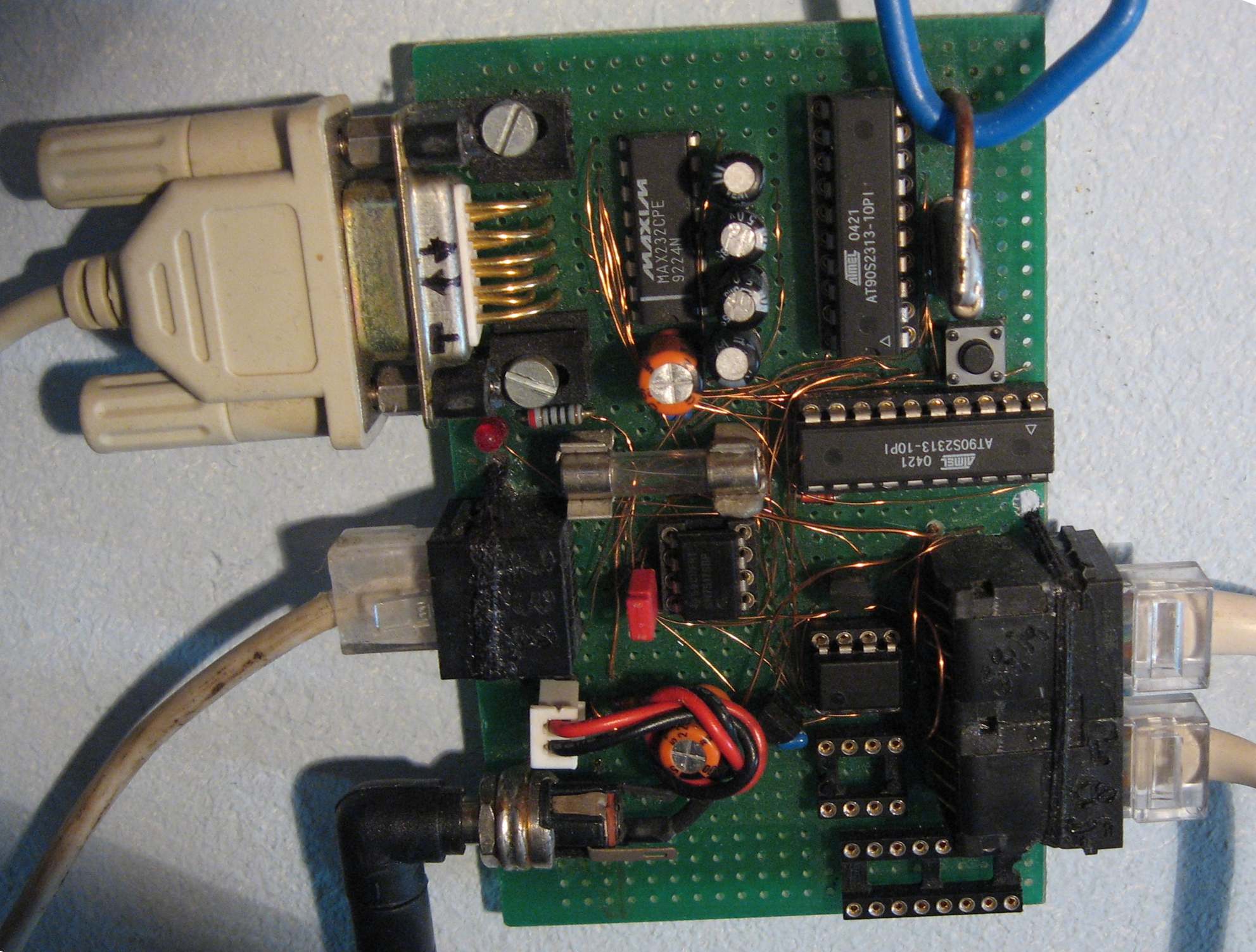
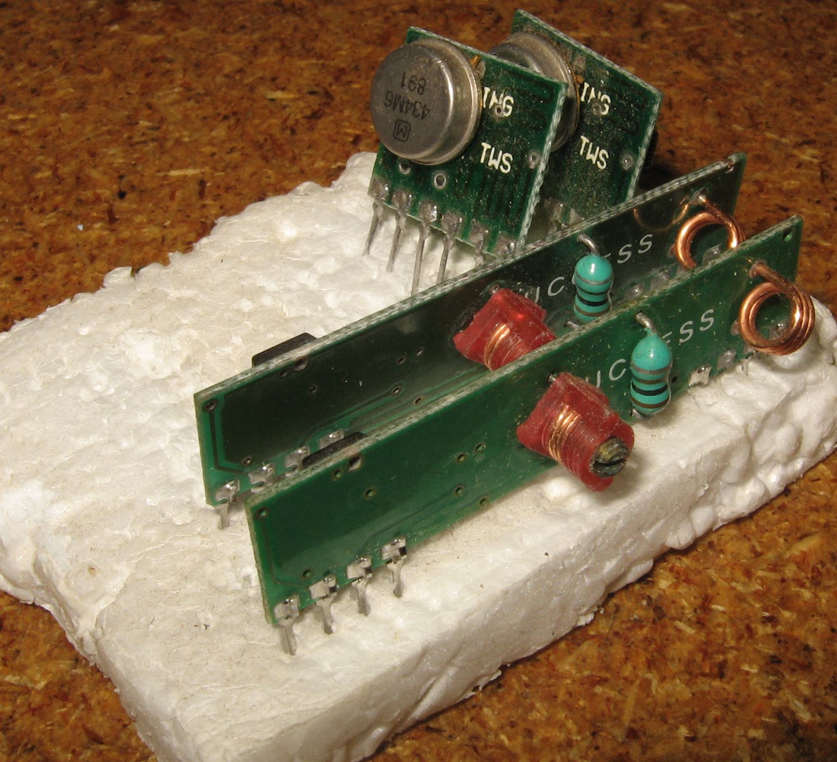

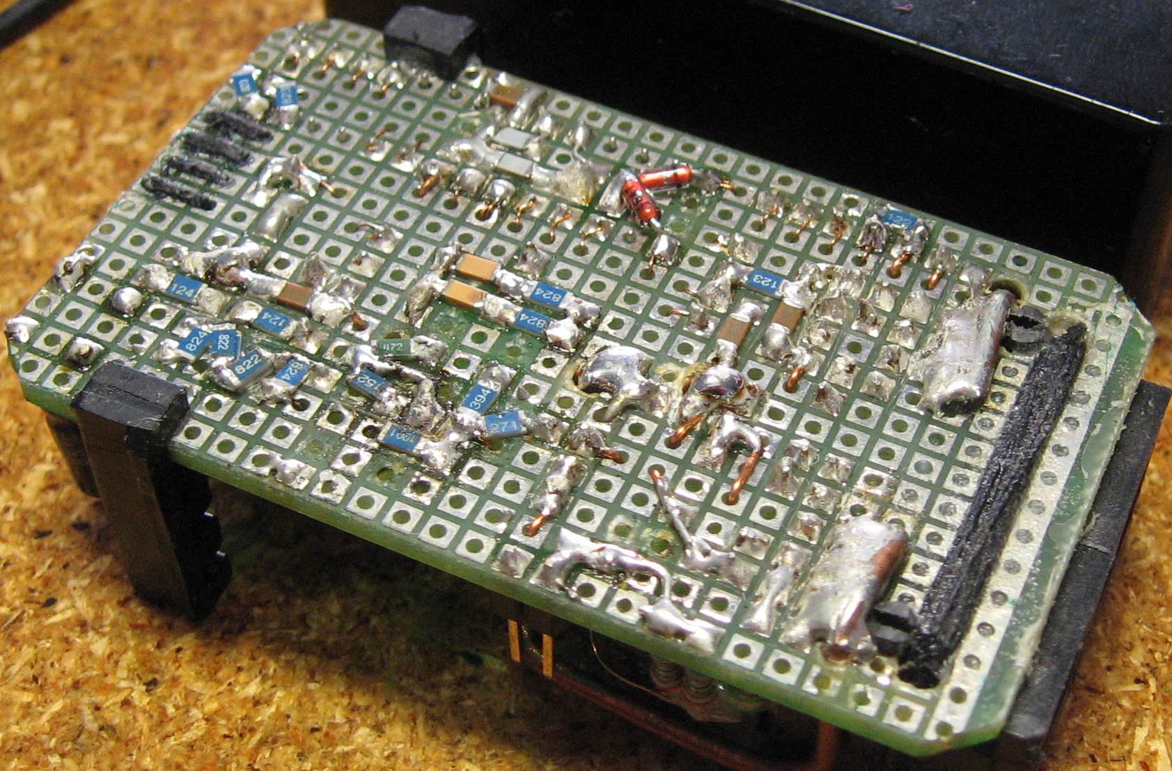
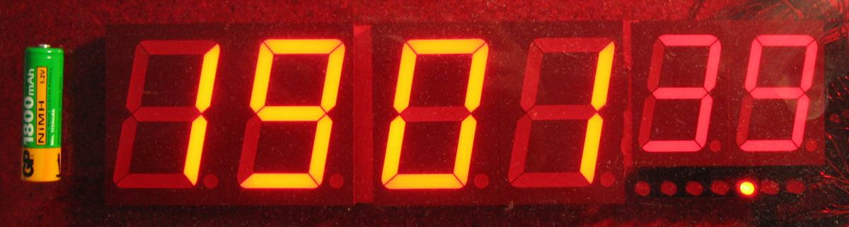
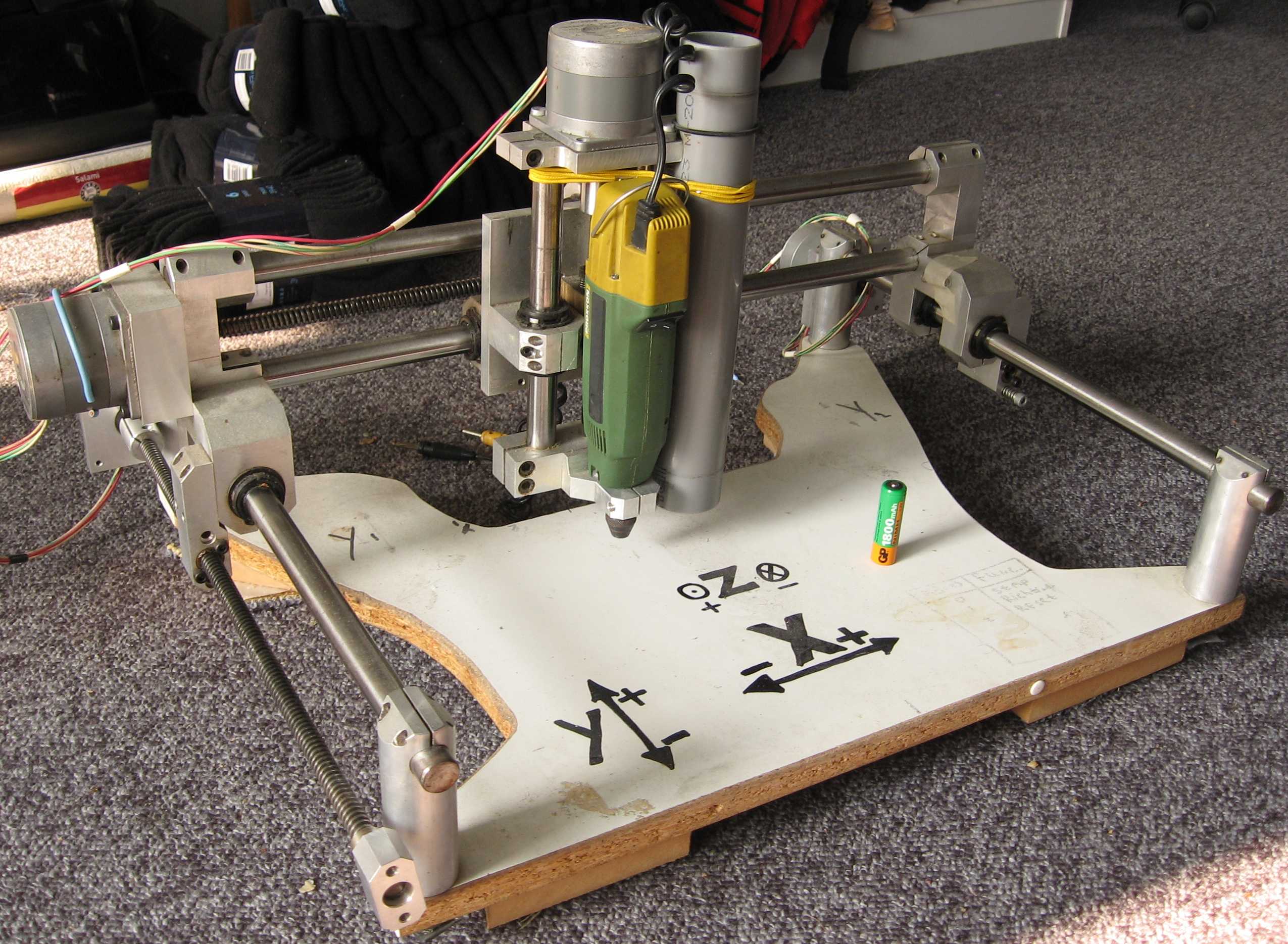

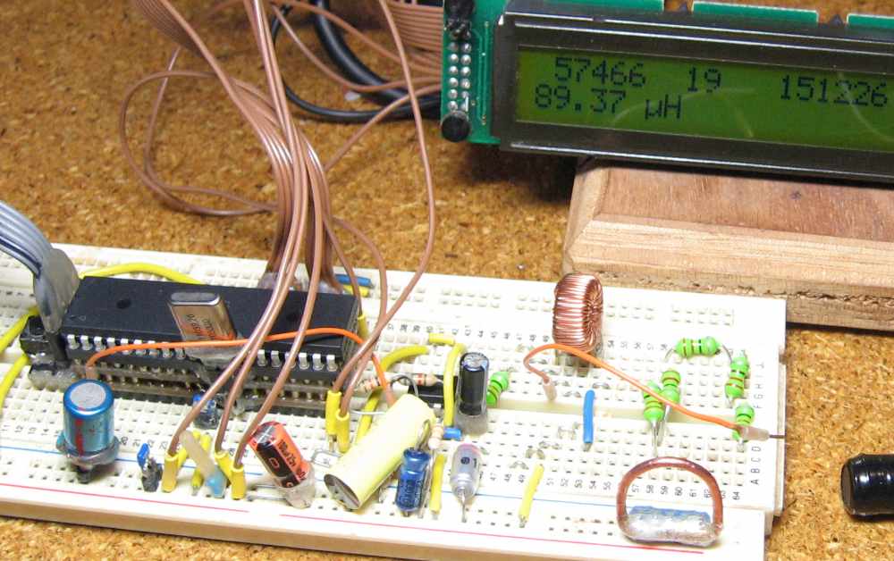
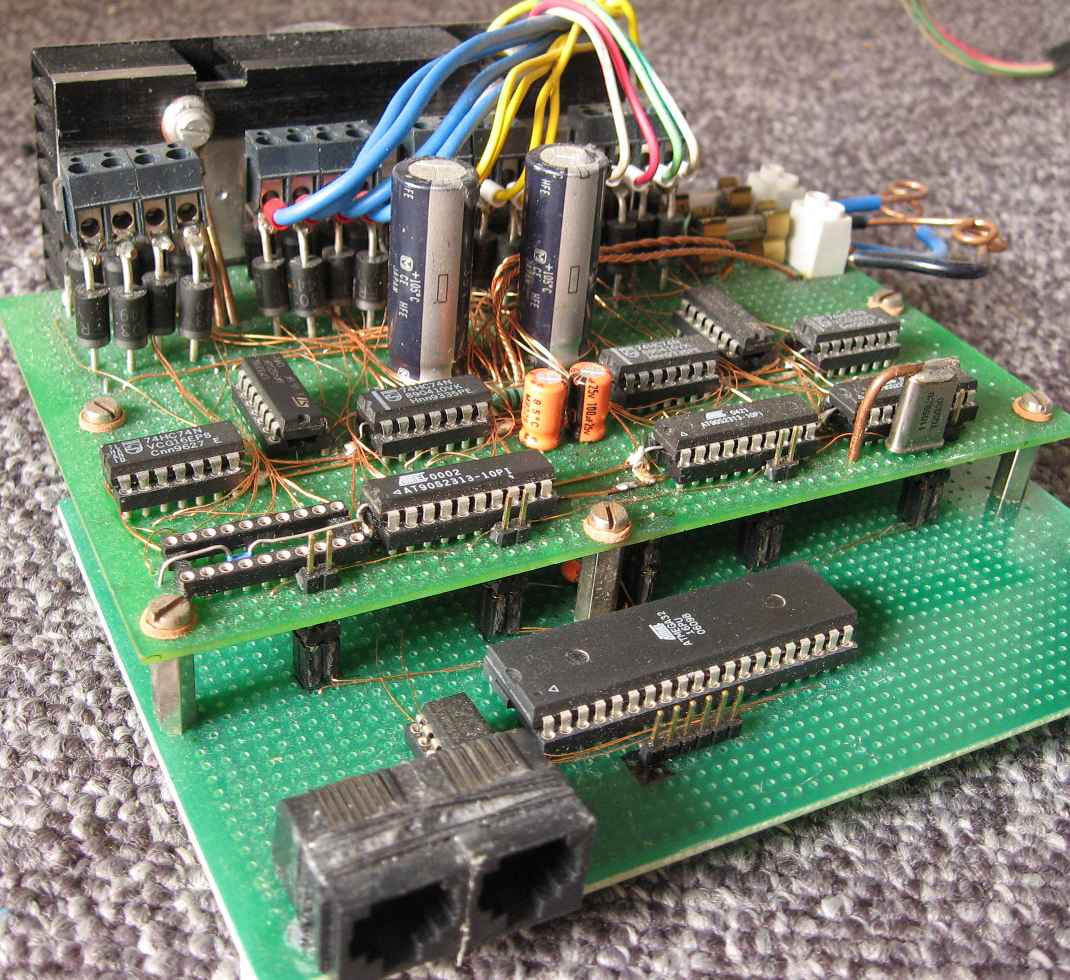


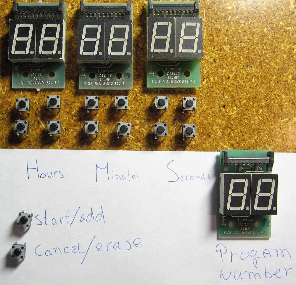

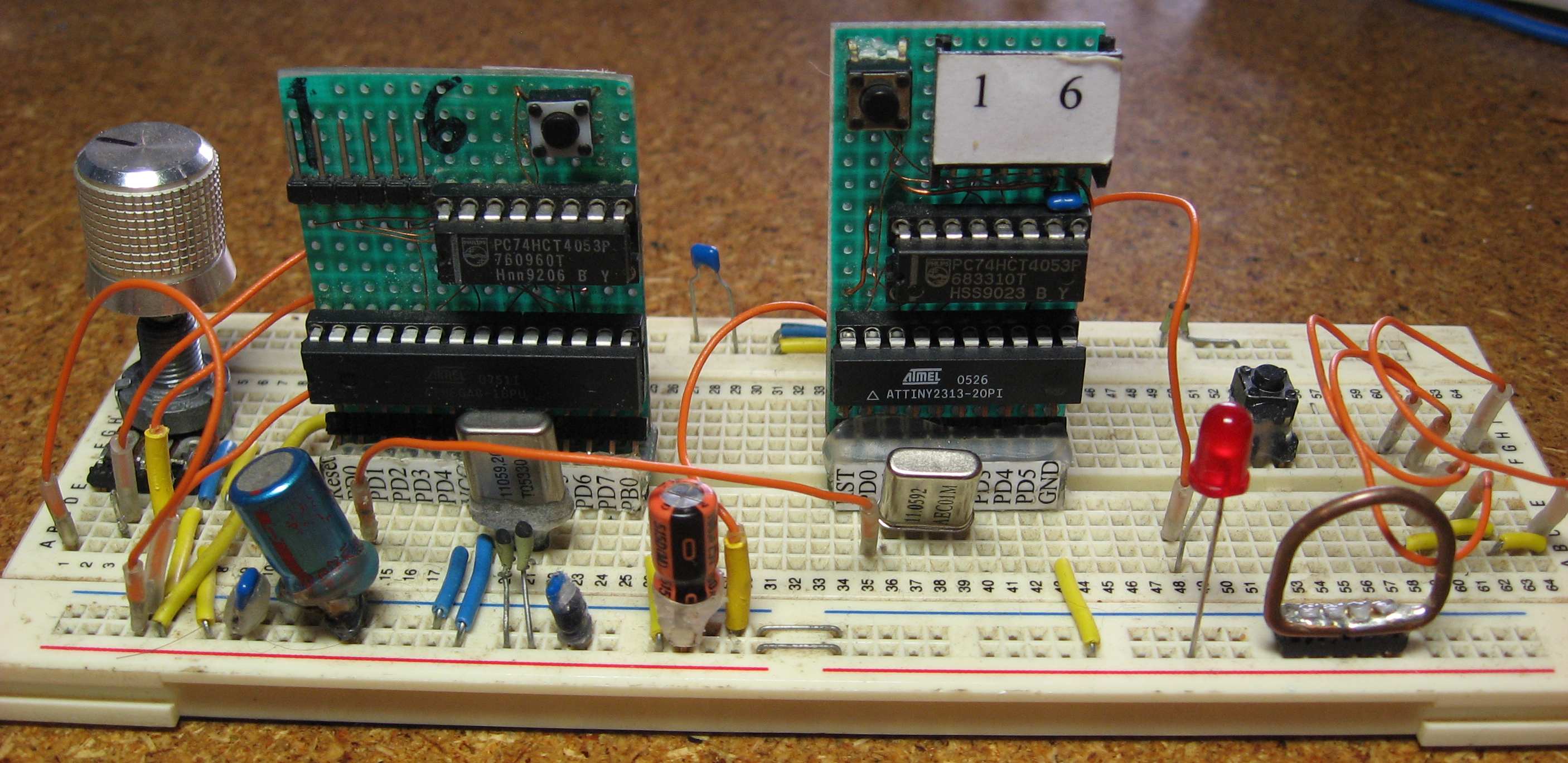

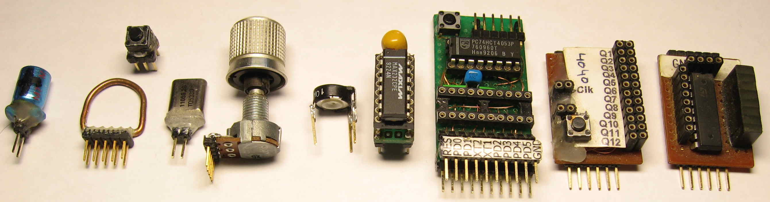
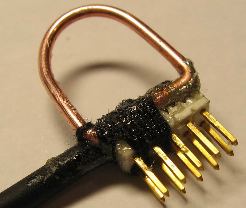